The Teletype Model 28 · Volume 8
The Teletype Model 28 — Vol 8: Wiring a 28, and the 28-or-15 Decision
A 28 accepts a 20 or 60 mA neutral loop, or a polar line through a relay, depending on how its electrical service unit is strapped, and some military 28s accept neither. This volume covers what is specific to wiring a 28, how one can print the news again from RTTY.COM's ITTY streams, how it compares with the Model 15, and how a pair of them could serve a PURPLE cipher machine replica.
8.1 What belongs here and what belongs elsewhere
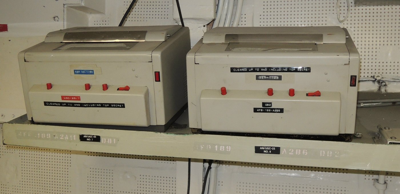
Interfacing Teletypes and Paper Tape covers the general methods of connecting any of these machines to a computer or a radio: loop supplies, isolation, serial timing, Baudot conversion, terminal units, software. This volume covers only what is particular to the 28: how its selector is strapped, what its electrical service unit contains, where its keyboard sits in the loop, the low-level military sets, and its speeds. Then it compares the 28 with the Model 15 and applies both to a real project.
8.2 The 28’s signal, in numbers
Table 1 — The 28's signal, in numbers
| 60 wpm | 75 wpm | 100 wpm | |
|---|---|---|---|
| Operations (characters) per minute | 368 | 460 | 600 |
| Baud, 7.42-unit code | 45.45 | 56.9 | 74.2 |
| Element length | 22 ms | 17.6 ms | 13.5 ms |
| Character length (7.42 units) | 163 ms | 130 ms | 100 ms |
| Bulletin 216B “dot cycles” per second | 22.8 | 28.5 | 37.1 |
Every 28 uses the 7.42-unit start-stop code: one start element, five data elements, and a stop element 1.42 units long, the Bell System standard. Western Union and some other users ran 7.00-unit code with a one-unit stop, which needs different gear sets (Volume 7). Haynes explains that “60 wpm” is really 367.52 operations per minute divided by six characters per word, or 61.25 words, “usually rounded down to 60.” Signals are neutral (current and no current) unless the set has been arranged for polar working.
8.3 The selector: 20 or 60 milliamperes
Bulletin 216B is explicit. The equipment “will operate on signal line current of either 20 or 60 milliamperes without a line relay,” and “is wired at the factory for operation on 0.060 ampere signal line current but, by making a convenient wiring change in the Electrical Service Unit and readjusting the selector armature spring, it may be adapted for operation on 0.020 ampere signal line current.”
The change is in how the two selector coils are connected. The 1953 bulletin gives each coil as 132 ohms, and a terminal board in the electrical service unit connects them in series for 20 mA or in parallel for 60 mA. The technical data in section 573-115-100 says the same: “Selector coils in series .020 amperes; Selector coils in parallel .060 amperes.”
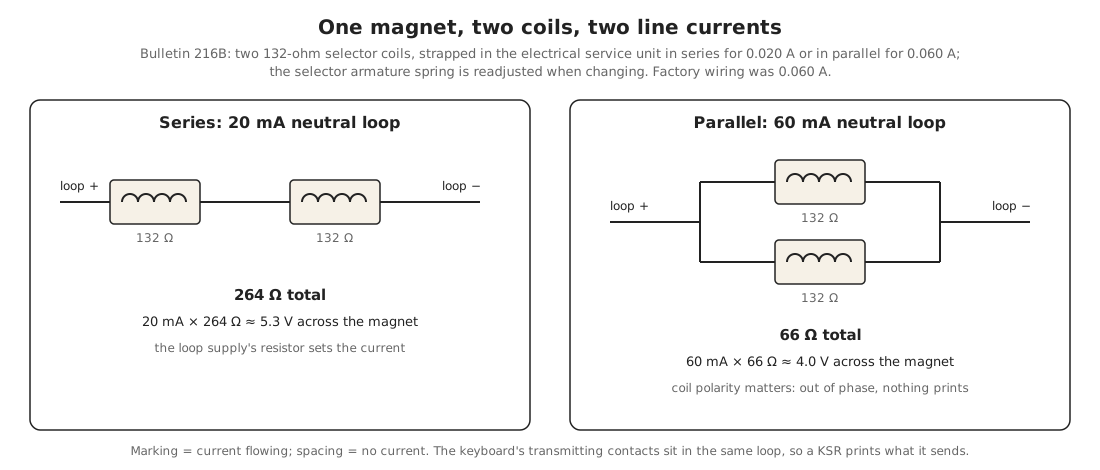
Some practical points follow:
- Measure before connecting anything. At the selector connector or the ESU terminal board, the DC resistance tells you how the coils are strapped. Bulletin 216B’s figures give about 264 ohms in series and 66 in parallel. Irvin Hoff, writing for amateurs in about 1965, gave rounder figures for the coils he measured: “about 50 ohms” means parallel and “about 200 ohms” means series. Either way, a low reading is the 60 mA strapping, which amateurs almost always used.
- Hoff also gives the inductance, “around 3 Henries for a model 28” per coil. That inductance is why a loop supply needs a high voltage and a series resistor to make the current rise quickly, and why the coil produces a large voltage spike when the current is switched off. Making the Parts That No Longer Exist describes the DeRamp interface board, which recovers that energy instead of burning it in a resistor.
- Coil polarity matters in parallel. Hoff warns that if the two coils are connected in parallel the wrong way round, the magnet does not pull properly and nothing prints. Swapping one coil’s leads fixes it.
- Change the armature spring if you change the strapping. The spring is adjusted for one current. After changing between 20 and 60 mA, refine the spring for the best range (Volume 6).
- Hoff’s “30 mA” for series. Hoff wrote that series magnets “need a 30 ma. circuit.” Teletype’s documents say 20 mA. Use Teletype’s figure. A series-strapped selector will work at 30 mA, but the bulletins specify 0.020 A.
8.4 The electrical service unit
The LESU is the 28’s junction box, and it decides how the machine connects to the world. Bulletin 216B lists its contents and options: receptacles, fuses and switches for the power and signal circuits, with optional motor control, “signal line relay mounting assembly,” “0.100 ampere rectifier assembly,” “current limiting resistors for operation of the Model 28 Printer on DC,” and a “line test key assembly.” Later descriptions add the line (polar) relay, a line shunt relay, terminal blocks and the interconnecting cables (BSP 573-101-100TC, §3.09).
Three of these matter most to an owner today:
- The line test key. On sets that have it, the key switches the machine between LINE and TEST. In TEST the keyboard drives the typing unit on a local loop, so the machine types like a typewriter with nothing connected. Restoring a Teletype uses it as the first test after restoration. Stickelman’s restored 28 ran “in ‘test’ mode, where the device ignores the signal loop and behaves like a typewriter.”
- The rectifier. The optional 0.100 A rectifier supplies the selector magnet and relay bias windings, but Bulletin 216B warns that it “does not have sufficient output to also supply the signal line current.” A 28 with a rectifier still needs a loop supply.
- The line relay. Where a set was used on a polar line (current in one direction for mark, the other for space), a polar relay in the ESU drives the selector locally. A set with a polar relay fitted (one recent listing called itself a “KSR Mark II with polar relay”) can usually be returned to neutral working by removing or bypassing the relay according to the set’s wiring diagram. For transmitting, Bulletin 216B says the equipment “is wired at the factory to transmit neutral signals but is readily adaptable to transmit polar signals by wiring changes.”
The electrical service unit is where 28 sets differ most from one another, so the wiring diagram for the specific ESU code (LESU5/103, LESU7/147 and so on) is essential before connecting anything. RTTY.COM has several 28 KSR and ASR wiring diagrams (Volume 6).
8.5 The keyboard in the loop
On a standard KSR, the keyboard’s transmitting contacts are in series with the selector magnet on the same loop. That is why a KSR prints what it sends, and why pressing BREAK opens the loop and stops the other station. It also means:
- For a computer to send to a KSR and receive from it on one loop, the computer must see its own echo. Everything the keyboard sends is also printed locally by the 28.
- To separate send and receive, the keyboard contacts and the selector must be brought out to separate terminals. Whether that is a terminal-block change or a rewiring job depends on the ESU and its wiring diagram. Interfacing Teletypes and Paper Tape covers both arrangements.
The compact Navy KSRs (AN/UGC-20 and its relatives) are different. Their keyboard is an electrical unit with a separate distributor, not the LK’s signal generator. navy-radio.com notes that the UGC-20B “has a built-in 60ma keyer (or can output 1.5v/70uA directly from the photocells).” Check which keyboard a compact set has before planning the loop.
8.6 The low-level trap
From the 1960s, the Navy’s secure circuits (CRITICOM, and later TEMPEST installations) used low-level signalling: ±6 V polar signals to MIL-STD-188B, in place of a 60 mA loop, with heavy shielding to stop the machines radiating what they printed. Teletype made 28s for these circuits, and many survive:
- AN/UGC-49, low-level 28 ASR, “MIL-STD-188B six volt polar interface and Teletype’s TEMPEST feature”;
- AN/UGC-77 and AN/UGC-91 (weather), low-level compact KSRs;
- TT-603/UG, low-level miniature TD; TT-605/UG, low-level miniature ROTR, with an Electronic Service Assembly and double-shielded selector magnets;
- AN/UGC-50 and AN/UGC-51, low-level versions of the skintight TT-306 and TT-307, converted by kits MK-1114/UG and MK-1115/UG.
These machines do not have an ordinary loop interface. Their selectors are driven by electronics that expect ±6 V signals. They can be used, with an interface built for that signal or by converting the selector circuit back to a loop. A buyer should know before paying for one, and should expect more work than with a standard 28.
8.7 Printing the news again: ITTY
When the 28 was in service, much of what it printed was news: the AP and UPI wires came in on teleprinters in every newsroom and broadcast station. That kind of traffic still exists, for teletypes. RTTY.COM runs ITTY, “a live audio stream that encodes Baudot RTTY signals just as the AP and UPI wire services did for fifty years.” It is free, needs no login, and runs 24 hours a day from Arvada, Colorado. Route the audio to a terminal unit connected to a teletype, the site explains, “and the news prints continuously in ALL CAPS on paper — exactly as it would have in 1965.”
Table 2 — Printing the news again: ITTY
| Channel | Speed | Tones (mark / space) | Content | Stream |
|---|---|---|---|---|
| ITTY | 60 wpm, 45.45 baud | 2125 / 2295 Hz | Wire-service news articles, loaded daily | internet-tty.net:8000/ITTY |
| ITTY 100 | 100 wpm, 75 baud | 2125 / 2295 Hz | The same news at 100 wpm | internet-tty.net:8010/ITTY100 |
| AUTOSTART | 60 wpm, 45.45 baud | 2125 / 2295 Hz | A daily “This Day in History” bulletin, user articles, selected Greenkeys messages | internet-tty.net:8030/AUTOSTART |
| ITTY Europe | 66 wpm, 50 baud | 1275 / 1445 Hz | European news from RSS feeds | internet-tty.net:8040/EUROPE |
The signal chain is the same as for radio RTTY. The stream’s audio goes into a terminal unit (or a sound-card demodulator driving a loop interface), and the terminal unit’s loop output goes to the 28. RTTY on the Air explains terminal units, RTTY.COM has schematics of the classic ones, and Interfacing Teletypes and Paper Tape covers the full setup.
ITTY is especially useful for a 28 for three reasons:
- A 100 wpm 28 has something to print. Many surplus 28s are geared for 100 wpm (Volume 7). The ITTY 100 channel sends the same news at 75 baud, within about one percent of the 28’s 74.2 baud and well inside its range.
- It tests a gear change. After changing gears, run both channels. A machine that prints ITTY cleanly at its new speed is correctly geared and ranged.
- It is a long soak test. A newly restored 28 can print for hours without anyone typing, which is how slipping clutches, sticking levers and overheating motors show themselves.
The AUTOSTART channel takes contributions through a small program, RTTYMailer, so a message typed today can come back off a 28 in Baudot.
8.8 The 28 or the 15?
The Model 15 and Model 28 are the two machines most often considered for a first teletype, and for a project like the one below. The Teletype Model 15 covers the 15 in the same depth as this dive covers the 28. The comparison:
Table 3 — The Model 15 and Model 28 are the two machines most often considered for a first teletype, and for a project like the one below. The Teletype Model 15 covers the 15 in the same depth as this dive covers the 28. The comparison
| Model 15 | Model 28 | |
|---|---|---|
| In production | 1930 to about 1963 | 1950/53 to about 1981 (end date not firmly documented) |
| Frame | Cast iron | Stamped sheet metal; “no structural castings” |
| Printing | A basket of type bars | A removable type box, one hammer |
| Clutches | Felt friction clutches | Six all-steel internal-expanding clutches |
| Design speed | 60 wpm normal; 75 wpm maximum design (Haynes) | 100 wpm design; 60, 75, 100 wpm by gears |
| Character set | Fixed by the type bars | Changed by swapping the type box |
| Extra functions | Few | The stunt box, with 42 slots |
| Tape | Separate Model 14/19 equipment | Integrated ASR and a full family of tape units |
| Lubrication | Felt clutches every two weeks (The Teletype Story) | Typing unit every 6–12 months by speed (573-115-701) |
| Noise | Heavier, thudding | Quieter by design; “all those little parts moving” (Haynes) |
| KSR weight | About 200 lb for a TT-5/FG set (see the 15 dive) | About 130 lb (floor), 110 lb (wall) |
| Loop | 60 mA | 20 or 60 mA by strapping; polar by relay |
| Repair | Large, robust parts; easy to see what is happening | Many small parts; more adjustments; better documented by BSP |
| Parts | Large stock of used parts | Large stock, and many parts shared with the Model 35 |
| Character | The classic 1930s–40s machine | The classic 1950s–70s machine, Navy grey with red function keys |
In short, the 15 is simpler, heavier, slower, and closer in date to the 1941 machines. The 28 is faster, quieter, lighter, more capable, has a full tape family, and needs more patience with small parts. Either one, in good order, prints five-level Baudot reliably at 60 wpm.
8.9 A pair for PURPLE
8.9.1 The project
I am building a replica of PURPLE, the Japanese diplomatic cipher machine of 1939–41, as described in the PURPLE series on the Iconic Machines site. My design (PURPLE Volume 10) uses a Raspberry Pi Pico controller, a keyboard, a thermal receipt printer, a plugboard and a set of stepping switches. Its printer section adds: “A vintage teleprinter is the faithful alternative and the subject of its own project.” The original machines used electric typewriters for input and output. For my replica I would like two machines in the same spirit, and I am considering three options: a pair of teletypes, Model 15 or Model 28, or a pair of IBM Wheelwriter 5 typewriters. Nothing has been bought yet. The Teletype Model 15 covers the 15 version of this question. This section covers the 28.
8.9.2 How a 28 pair would fit
The replica’s design already matches a teleprinter closely:
- The character set. The replica works in 26 letters plus GARBLE (on the space bar), FIGS, RESET and LINE FEED. Positions are typed “as numbers with FIGS held down: as on a teleprinter, the top letter row Q W E R T Y U I O P then gives the digits 1 to 0” (PURPLE Vol 10). That is exactly the 28’s communications keyboard, which has figures on the upper case of the top letter row.
- The output format. The replica prints its output “in groups of five” and logs it. A 28 with its 85-character line holds a comfortable 10 groups of five per line (59 characters with spaces) before the controller sends CR and LF.
- The speed. At 60 wpm a 28 prints six characters a second, much faster than anyone would key a PURPLE message by hand.
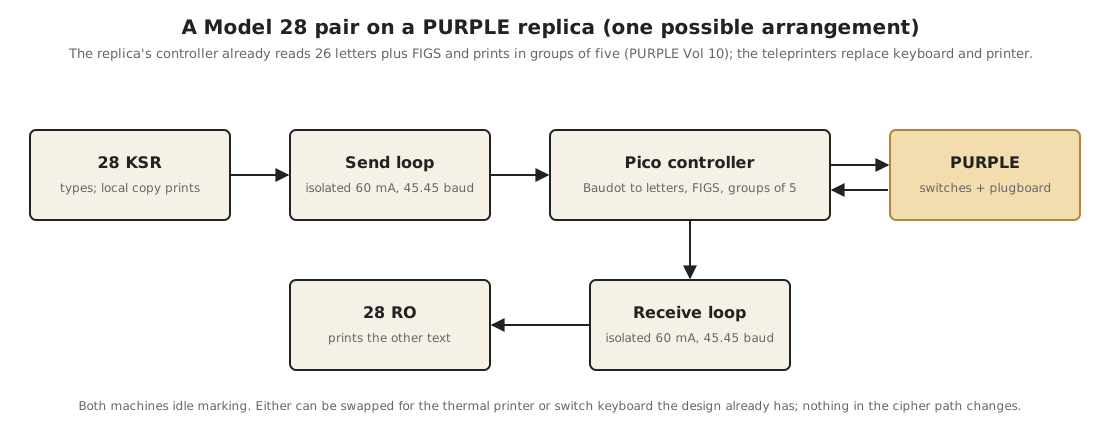
The arrangement in the figure uses a KSR for input and an RO for output:
- The operator types on the 28 KSR. Its keyboard contacts key a send loop to the controller, and because the KSR’s own selector is on that loop, it prints what was typed. That gives a paper copy of the input, as the original’s input typewriter did.
- The controller converts each Baudot character to a letter and steps the PURPLE switches. It keeps track of the shift state, because on a teletype FIGS is a character that shifts until LTRS (or, with unshift on space, until a space), not a key held down. The controller’s keyboard logic has to treat it that way.
- The enciphered or deciphered letter goes out on the receive loop to the 28 RO, grouped in fives, with CR and LF inserted every ten groups.
The other details:
- Both machines at the same speed, most simply 60 wpm. A 28 geared for 100 wpm needs a gear change (Volume 7), or the controller can send to it at 74.2 baud.
- Isolated loop interfaces on the Pico for each machine. Interfacing Teletypes and Paper Tape covers the circuits. The replica’s other circuits are at 5 and 24 V; a loop supply is much higher, and the selector’s inductive spike is large. Keep the loops galvanically separate from the Pico.
- RESET needs a key. The 28 keyboard’s FIGS case has characters the replica does not otherwise use (BELL, for instance), and the controller can treat one of them as RESET.
- The thermal printer path stays. As in the 15 version, the replica should still work with its thermal printer and switch keyboard while either 28 is under repair.
- A single KSR is also possible. One 28 KSR can do both jobs: the operator types a group, it prints the input, and the controller then prints the output on the same machine. That halves the iron but mixes input and output on one sheet, unlike the two typewriters of the original.
8.9.3 Model 28 or Model 15 for PURPLE?
Table 4 — Model 28 or Model 15 for PURPLE?
| Consideration | Favours |
|---|---|
| Closest in date and look to 1941 | 15 |
| Quieter in a house; less oil; lighter | 28 |
| Both input and output in a matched pair | Either |
| Easier to find a matching KSR and RO | 28 (ROs are common) |
| Fewer small parts to adjust | 15 |
| Tape (to punch an intercepted message and replay it) | 28 (ASR or tape units) |
| Electric typewriters “like the original” | Neither: the Wheelwriter option |
8.10 Closing
The 28 was designed in the 1940s to do in sheet metal what the Model 15 did in cast iron, twice as fast and with far less upkeep, and it did that for thirty years in Navy message centres, telephone company offices, airline weather rooms and ham shacks. Surviving machines are still being cleaned, oiled and ranged by restorers who work from the same Bell System Practices that the original servicemen used. Connected to a terminal unit and RTTY.COM’s ITTY stream, a restored 28 can print the news again like a wire-service machine, and connected to a microcontroller it can type and print for a machine like PURPLE.
8.10.1 Sources (Vol 8)
- 🔴 Primary source: Teletype Corporation, Bulletin No. 216B (June 1953): 20 or 60 mA without a line relay; factory wiring for 0.060 A and conversion to 0.020 A by rewiring in the ESU and readjusting the armature spring; two 132-ohm coils in series or parallel; factory neutral transmission adaptable to polar; ESU contents and options (motor control, line relay mounting, 0.100 A rectifier that cannot supply the line current, DC current-limiting resistors, line test key); signalling frequency in dot cycles (22.8, 28.5, 37.1). https://bitsavers.org/communications/teletype/28/216B_Model28_Descr_Jun53.pdf
- Selector coil currents in the technical data. BSP 573-115-100, in NAVSHIPS 0967-173-7010 (1967). https://www.navy-radio.com/manuals/tty/0967-173-7010-6707.pdf
- Line (polar) relay, line shunt relay and line test key in the ESU; LINE/TEST operation. BSP 573-101-100TC and the 28 ASR operating instructions, in NAVSHIPS 0967-173-6010 (Bulletin 312B, Vol 1). https://www.navy-radio.com/manuals/tty/312b-v1-orig-6707.pdf
- Coil resistances measured by amateurs (about 50 and 200 ohms), about 3 H per coil, series “30 ma.,” parallel 60 mA, coils out of phase. Irvin M. Hoff, K8DKG, Introduction to Amateur Radio Teletype. https://www.rtty.com/development/literature/introduction.htm
- 7.42-unit and 7.00-unit code, 367.52 operations per minute, 61.25 wpm; 100 wpm design maximum; about 13.5 ms elements at 100 wpm; Model 15 design maximum 75 wpm. Jim Haynes, Some Notes on Teletype Corporation. https://deramp.com/downloads/mfe_archive/030-Terminals/Teletype/History/haynes—notes.pdf
- Low-level sets (AN/UGC-49, -50, -51, -77, -91; TT-603, TT-605; MK-1114/1115), MIL-STD-188B, TEMPEST; UGC-20B keyer and photocell outputs; UGC-25 aboard USS Midway. navy-radio.com, “US Navy Teletype Equipment” and “AN/UGC-77 Teletype RFI Compact 28KSR (TEMPEST) Info.” https://www.navy-radio.com/tty.htm
- ITTY: four channels, speeds, tones, ports, content, Arvada, RTTYMailer, “exactly as it would have in 1965.” RTTY.COM, “ITTY — Live Teletype Wire Service” (read 3 November 2026). https://rtty.internet-tty.net/itty.html
- Test mode on a restored 28; the DeRamp interface. David Stickelman, “Model 28 KSR Wall Mount Progress” (12 Nov 2024). http://stickelman.net/index.php/2024/11/12/model-28-ksr-wall-mount-progress/
- “KSR Mark II with polar relay” listing. PicClick, “Teletype Model 28” (read 3 Nov 2026). https://picclick.com/Popular/teletype-model-28
- Comparison table, Model 28 column. Volumes 1–7 of this dive and their sources; The Teletype Story (1957) on castings and lubrication intervals.
- The PURPLE replica: Pico controller, thermal printer, FIGS-held digit entry on the top row, GARBLE on the space bar, RESET, LINE FEED, groups of five, “a vintage teleprinter is the faithful alternative.” PURPLE, Volume 10, “Building a PURPLE — Design,” Iconic Machines. https://iconic-machines.fubsypoly.com/purple/vol-10/
- Cross-links: Interfacing Teletypes and Paper Tape (https://dots-and-dashes.fubsypoly.com/interfacing-teletypes-and-paper-tape/); The Teletype Model 15, especially its Vol 8 on a Model 15 pair for PURPLE (https://dots-and-dashes.fubsypoly.com/teletype-model-15/); RTTY on the Air (terminal units); Making the Parts That No Longer Exist (the DeRamp regenerative loop interface); Restoring a Teletype (test mode).