The Teletype Model 28 · Volume 6
The Teletype Model 28 — Vol 6: Adjustment, Range and Repair
The 28's adjustment sections run to hundreds of pages, but a working machine needs only a few dozen of those adjustments checked, and the Bell System listed which ones. This volume covers that shortlist, how to take and read a range, the faults that surplus 28s actually develop, the tools and parts, and where the help is, starting with RTTY.COM.
6.1 Read before you turn a screw
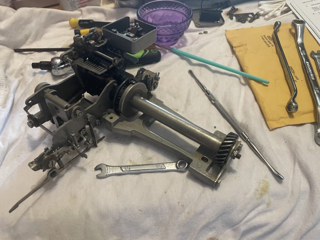
Every adjustment on a 28 is specified. Each unit’s adjustment section (numbered -700) gives, for each part, a requirement (a clearance, a position or a spring tension in ounces or grams) and a “to adjust” procedure. The typing unit’s section, 573-115-700TC, was at Issue 7 in the Navy’s 1967 manual. The keyboard (573-116-700), electrical service unit (573-133-700), cabinets (573-134-700) and motors (570-220-700) have their own, and the ASR units have theirs in Bulletin 312B, Vol 2. The older combined bulletin is 217B, Adjustments and Lubrication, Model 28 Printer.
Three rules from the sections themselves are worth taking to heart before starting:
- Adjustments are in order. “The adjustments of each unit are arranged in a sequence that should be followed if a complete readjustment of the unit were undertaken” (573-134-703TC, §1.04, the same wording appears throughout). Many adjustments depend on earlier ones. Changing one in the middle of the list can upset several that follow.
- Shims go back where they were. “If a part mounted on shims is removed, the number of shims used at each of its mounting screws should be noted so that the same number is replaced when the part is remounted.”
- Tighten what you loosened. “After an adjustment is completed, be sure to tighten any nuts or screws that are loosened.”
A fourth rule is not in the sections but comes from everyone who has restored one: a 28 that prints correctly should not be readjusted. These machines were adjusted at the factory and in service by people who did it every day. Most surplus 28s need cleaning, oil and a few specific repairs, not a complete readjustment. Change an adjustment only when a check shows it is out of limits, or when a part has been replaced.
6.2 The critical adjustments
The Bell System had the same problem on a larger scale: how could a serviceman decide quickly whether a machine was in good order without checking hundreds of adjustments? Its answer was a short list of critical adjustments, published as Bell System Practice 570-001-901, Teletypewriter Service Manual (Issue C, July 1967, Mountain States Telephone & Telegraph). A scan of the complete 102-page manual is on RTTY.COM. It covers the Model 14, 15 and 19, the Models 28 and 35 typing units, the 28 keyboard, the typing and non-typing perforator, the typing reperforator and the transmitter-distributor, and the Model 33.
It explains the idea plainly: “These critical mechanical adjustments are those that experience has shown to contribute most to trouble-free mechanical operation of teletypewriter apparatus. These adjustments are usually associated with a group of other connected and related adjustments. The verification of the critical adjustment can be an indicator of the connected and related adjustments.” A machine that meets them “will be in acceptable operating condition for trouble-free service.”
For each unit the manual gives an illustration, then a block-diagram check list in the order to follow, then the adjustment charts, each listing the BSP section to use if an adjustment is out of limits. For a restorer this is the best tool available. Work through the critical list for each unit. Where a check passes, leave the related adjustments alone. Where it fails, go to the full section for that adjustment and its neighbours.
The typing unit lubrication section adds its own short list of things to check at every lubrication (Volume 5): printing carriage position, printing hammer bearing stud, printing track, printing hammer stop bracket, carriage draw wire rope, and dashpot vent screw. These are the adjustments that wear or drift with use: the parts that move the type box and hammer at speed, and the cushion that stops the carriage.
6.3 Taking a range
6.3.1 What a range tells you
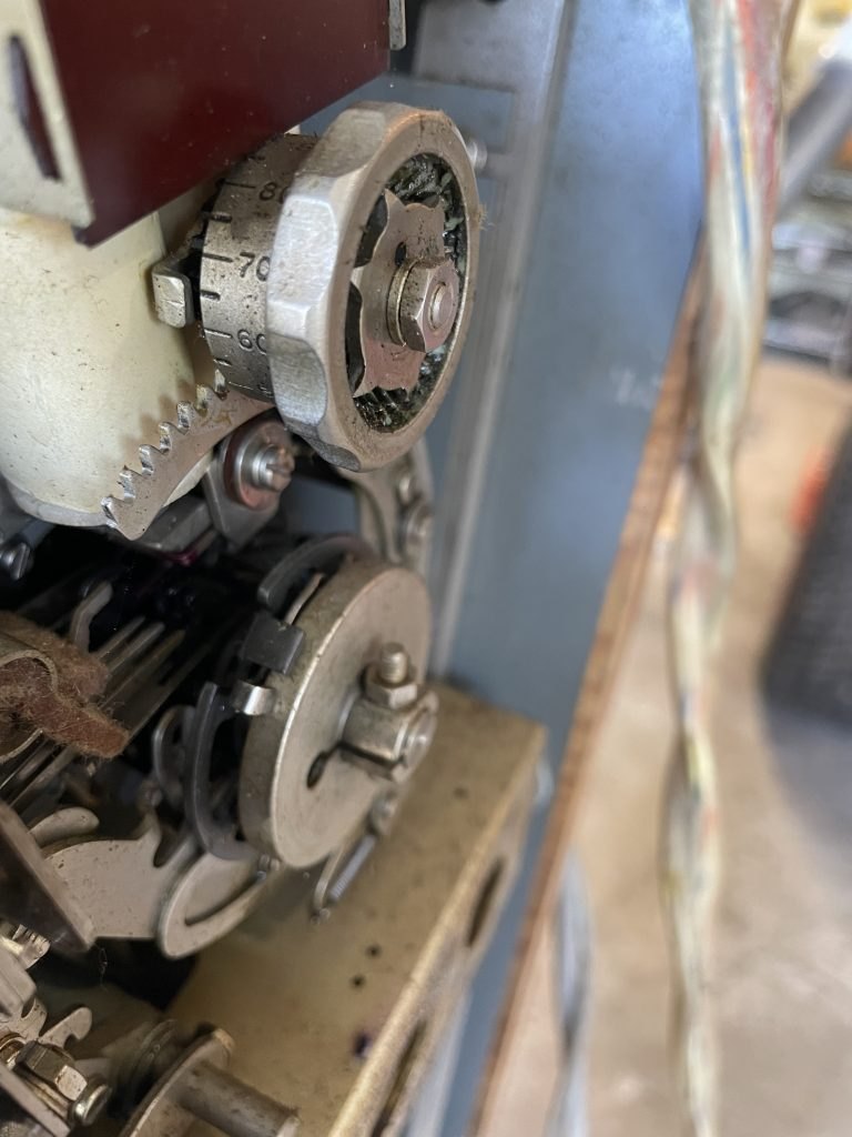
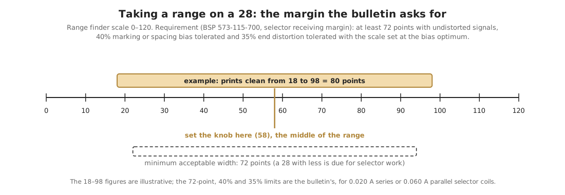
Restoring a Teletype explains taking a range in general: send a test message, turn the range finder from one end of the scale until errors start, then the other way, and read the two limits. The width between them is the machine’s margin for timing error. The middle is where the knob should be set. A wide range means a healthy selector. A narrow one means something in the selector is worn, sticky, badly adjusted or wrongly wired.
On the 28, the range finder moves the stop point of the selector cam-clutch (Volume 2), and the scale reads 0 to 120 points.
6.3.2 The numbers for a 28
There are two published standards, and they differ because they test different things.
The adjustment section (573-115-700, “selector receiving margin”). When “the condition of the components is equivalent to that of new equipment,” a distortion test set should show, at 60, 75 or 100 wpm and with the coils wired for either 20 mA (series) or 60 mA (parallel):
Table 1 — The adjustment section (573-115-700, "selector receiving margin"). When "the condition of the components is equivalent to that of new equipment," a distortion test set should show, at 60, 75 or 100 wpm and with the coils wired for either 20 mA (series) or 60 mA (parallel)
| Test | Minimum |
|---|---|
| Range with undistorted signals | 72 points |
| Marking or spacing bias tolerated | 40 percent |
| End distortion tolerated, scale set at the bias optimum | 35 percent |
The adjustment for these is the selector armature spring: “refine the selector armature spring” until the margins are met.
The critical adjustments manual (570-001-901, “check test receiving”). The station test is simpler: the receiving apparatus “should receive at least two complete lines of undistorted signals (the quick brown fox, etc.) without errors, with a selector range of at least 80 points. If distorted signals are available, and they are biased 20% both marking and spacing, the selector range should be approximately 40 points.” To set the scale, it says to take the upper limit with 20 percent marking bias and the lower limit with 20 percent spacing bias, and set the knob midway between them.
For a hobbyist with no distortion test set, the practical version is the second one: send the quick brown fox from a known-good source, measure the undistorted range, and expect 80 points or more on a machine in good order. Between 72 and 80 points, the machine works but is near the limit. Below 72, something needs attention.
6.3.3 Two adjustments to check first
Before blaming the selector for a poor range, check two adjustments in the selector section that affect the reading itself:
- Range finder knob phasing. “With range finder knob turned to either end of rack, zero mark on scale should be within 3 points of scribed line on range finder plate.” If the knob has been taken off and put back one tooth out, every reading is offset.
- Selector clutch stop arm. “Range scale set at 60. Selector clutch disengaged. Armature in marking position. Clutch stop arm should engage clutch shoe lever by approximately full thickness of shoe lever.”
6.3.4 A machine for two speeds
The adjustment section also gives a procedure for a 28 that must work at both 60 and 100 wpm, as many amateur machines with a gearshift do. Bias the selector internally between 0 and −7 percent at 100 wpm, take the receiving margins at both speeds, and set the knob at the common optimum, half the sum of the upper marking-bias limit at 100 wpm and the lower spacing-bias limit at 60 wpm. The requirement is that the printer “should accept signals with 35% bias and end distortion when operated at 60 or 100 wpm” at that one setting.
6.3.5 A signal to range with
The test needs a clean, known signal at the machine’s speed. The original equipment was a distortion test set, such as Teletype’s ED51 and ED58 (Bulletins 183B and 184B), which could add measured bias and end distortion. Today a computer and a loop interface can generate the same signals in software, including deliberate bias. Interfacing Teletypes and Paper Tape covers how. RTTY.COM’s ITTY streams (Volume 8) give a free source of continuous traffic at 60 and 100 wpm for a soak test once the machine is ranged.
6.4 Faults that surplus 28s actually have
Most of what goes wrong with a 28 today falls into a short list. Each item below has been reported by restorers or is described in Teletype’s own documents.
Table 2 — Faults that surplus 28s actually have
| Symptom | Likely cause | Where to look |
|---|---|---|
| Rhythmic clacking, mechanism does not move | Overload clutch has slipped because something is jammed. Bulletin 216B calls the clacking “an audible alarm” | Switch off, find the jam, turn the motor by hand until the lever drops back into its notch |
| Lamps on, motor does not turn | Thermal cutout has tripped (it resets by hand) | The reset button on the motor unit, in an awkward place on some cabinets |
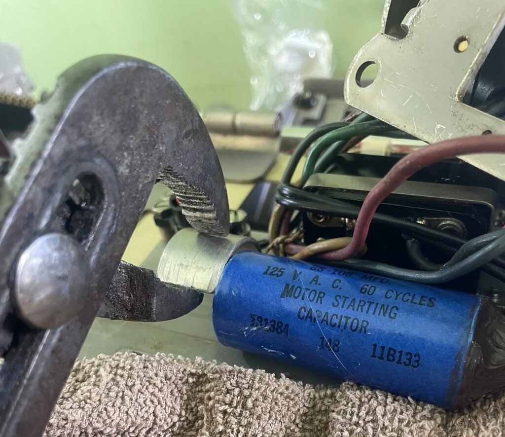
| Motor rocks back and forth, or starts slowly; cutout trips often | Starting capacitor has aged | Replace the capacitor (Bulletin 295B lists the part); see below |
| Squeal, worst when cold | Motor bearings with hardened grease | Strip and repack (Volume 5) |
| Prints a stream of blanks or garbage with nothing connected | Running open: no loop current looks like a continuous space | Normal; connect a loop or use the test position on the LESU (Restoring a Teletype) |
| Garbled copy with a good signal | Speed gears different from the sender’s; range finder badly set; oil on the selector armature; in parallel wiring, one coil reversed | Check the gears (Vol 7), take a range, clean the pole faces, check the coil polarity |
| Figures come out as letters after a space | Unshift on space is working as designed | Disable with the screw over its function pawl if needed (Vol 2) |
| Keyboard sends one character, then will not send again | A broken part in the keyboard’s reset linkage | The signal generator; Stickelman’s case below |
| Keyboard will not send at all | Keyboard locked by the LOCK key, by BREAK or BLANK on the line, or by a stunt box function | Press UNLOCK; then check the stunt box (Vol 2) |
| Machine will not print until a particular sequence, or stops printing | Selective calling or print suppression bars in the stunt box | Identify the extra function bars; remove or recode them |
| Motor stops after a minute or two of silence | Time delay mechanism and motor control: 86–172 s at 60 wpm | Normal; disable with the pilot screw if unwanted (Vol 2) |
| Carriage slams, bounces, or returns slowly | Dashpot vent screw or transfer slide; draw wire rope; spring drum tension | The six lubrication-time checks (Vol 5) |
| Double line feeds | The single/double line feed lever | Upper left rear of the typing unit |
| Faint or heavy print on multi-part paper | Printing spring bracket notch | Notch 1 for one to three copies, 2 for four or five, 3 for six or more (ASR operating instructions) |
| GFCI trips, cabinet shocks | Brittle motor lead insulation shorting to the frame | Restoring a Teletype, Vol 2 |
6.4.1 Two cases from a restoration
David Stickelman’s account of restoring a 28 KSR wall mount in 2024–2026 shows two of these in detail, and it is worth reading in full.
The keyboard that worked once. His keyboard sent one character and then had to be reset by hand. “The broken part was responsible for resetting the keyboard after a key was pressed, so you could press a key once, then manually had to reset the code bars to press a key again.” The repair meant “disassembling the ‘signal generator’, which is the assembly attached to the large geared shaft. This assembly has a bunch of tiny parts and I am surprised I didn’t lose anything. Reassembly took quite a bit of fiddling with adjustments, fortunately the manuals run through these.” Finding the fault took weeks of reading and asking (the case is described in Restoring a Teletype, Vol 2). The lesson is that the signal generator can be taken apart and reassembled by an amateur with the adjustment section open, but it is worth photographing every step.
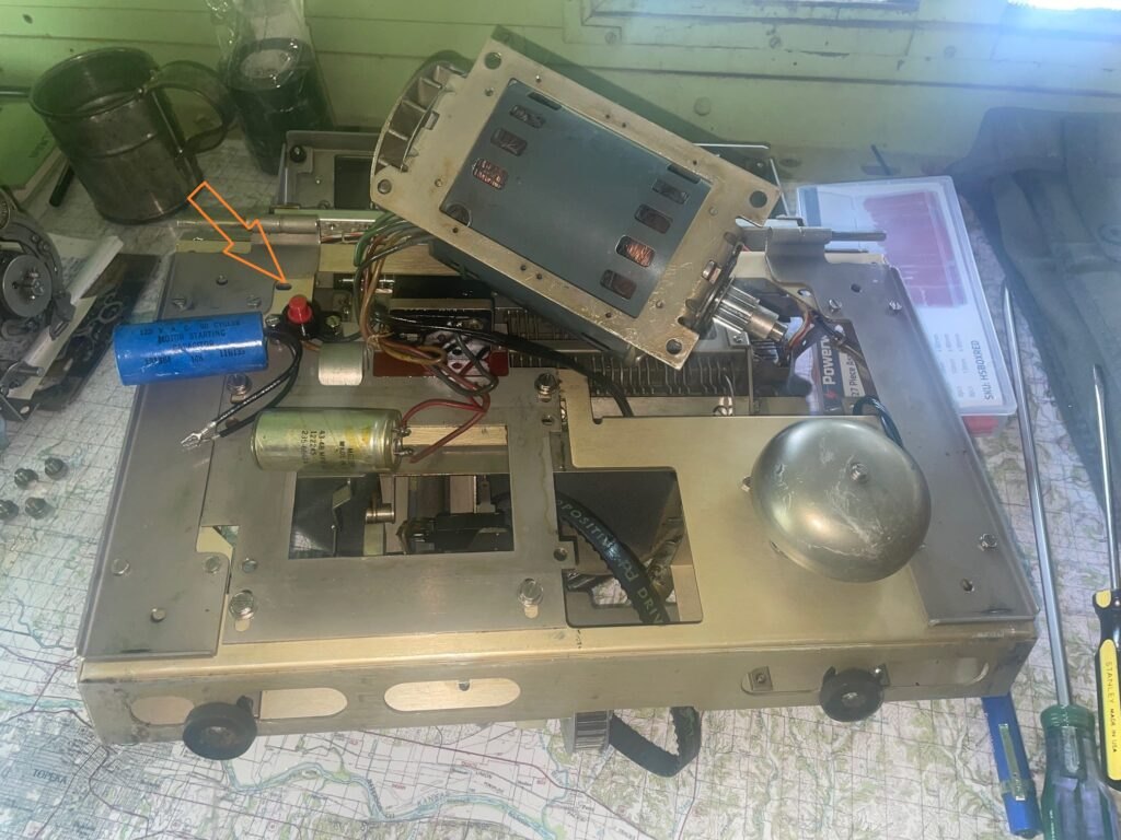
The motor that would not start. Two years later the same machine developed “motor bounce,” in which “the motor shaft bouncing back and forth, but never making a complete revolution,” and “weak start,” in which it turned but came up to speed slowly. The thermal cutout tripped often and had to be reset. He traced it to the starting capacitor, which “gives the heavy motor a kick to get it going,” and which, like any old capacitor, wears out. He found the part number in Bulletin 295B, moved the motor (four screws, after slackening the belt) to reach it, and fitted a new AC (non-polarised) motor-starting capacitor, soldering and heat-shrinking the leads instead of using spade terminals. After that, “startup is nearly instant and strong,” which matches every video of a healthy 28.
6.5 Tools
Teletype published a catalogue of its maintenance tools, section 570-005-800TC, Teletypewriter Maintenance Tools (Issue 6, August 1977). A scan is on RTTY.COM. It lists the spring scales that every “to adjust” procedure assumes, sets of thickness gauges from 0.002 inch upward in flat and round forms, wrenches and screwdrivers sized for Teletype hardware, spring hooks, a kit to add a degree disc to the handwheel so the shaft can be turned to exact angles, and a maintenance kit “to permit resting Model 28 and Model 35 typing unit on end for servicing.” The Model 28 cabinet’s lower panel can also be hung inside as a work shelf for the typing unit (Bulletin 216B).
A hobbyist can manage with less:
- Spring scales reading in ounces and grams. Many adjustments are spring tensions, and “close enough” is how a range shrinks.
- Feeler gauges, including round wire gauges for the clearances measured between curved surfaces.
- Screwdrivers and nut drivers that fit properly, so that no screw slots are damaged.
- Spring hooks (push and pull), which are essential for the dozens of small springs.
- A way to turn the shaft by hand: the motor’s handwheel, with the power off.
- Good light, a magnifier, and a camera. Photograph everything before taking it apart.
6.6 Parts
New Model 28 parts have not been made for decades. Parts come from:
- The parts bulletins, to identify what is needed: 1149B (the KSR and RO printer, keyboard, base, cabinet, motor and ESU), 1167B (typing reperforator and tape printer), 1169B (ASR), 1173B (tape splicer). Every part has a number, and parts sellers and Greenkeys members work by number.
- Parts machines. Incomplete 28s are common and cheap compared with complete ones (Volume 7). A second typing unit is the most useful spare a 28 owner can have.
- Specialist sellers. Stickelman recommends asking on Greenkeys, or “Mr RTTY,” for starting capacitors and similar parts. Individual parts, sub-assemblies and kits turn up on eBay (Volume 7 gives examples).
- Making them. Rubber, felt, some springs and nylon gears can be made or substituted (Making the Parts That No Longer Exist).
6.7 Where the help is
6.7.1 RTTY.COM
The single most useful website for a teletype owner is RTTY.COM (https://www.rtty.com/, which now redirects to https://rtty.internet-tty.net/). It is a non-commercial archive of radio teletype history, art and equipment, established in 1998, which describes itself as “the internet’s oldest RTTY resource.” It has no advertising or tracking and is hosted through SDF.org. It was founded by George Hutchison, W7TTY (now a Silent Key), with original software by Bill Bytheway, K7TTY, and content and operations by Tom Tillson, WB2TTY. The current owner and maintainer is Paul Heller, W2TTY. The site’s technical library carries the line “Original content copyright © 2011 William Bytheway K7TTY and George Hutchison W7TTY. Site maintained by W2TTY.”
For a Model 28 owner, the most useful parts of the site are:
- The Kretzman Technical Library (https://rtty.internet-tty.net/equipment.html), named for Byron W. Kretzman, W2JTP, “a tireless documenter of teletype technology.” Its stated aim is “to capture technical information for equipment that is no longer supported by the manufacturer.”
- The Teletype machines pages (https://rtty.internet-tty.net/equipment-teletype.html), with sections on the Model 28 ASR and Model 28 KSR/RO. The KSR/RO section has wiring diagrams WD2874, WD2875, WD2876 and WD2879 and the WO470 drawings. The ASR section has drawings of the ASR with LESU 13, LESU 29, the 415-9 pulse-com selector, and the 7/134,151 ESU. The same page covers tape equipment and transmitter-distributors.
- Service and documentation (https://rtty.internet-tty.net/equipment-service.html): the complete Bell System Practices Critical Adjustments Manual (570-001-901, above), with its Model 28/35 typing unit, Model 28 keyboard and perforator, typing reperforator and TD parts also split into separate files; the Western Union field service manual; the TTY maintenance tools catalogue; and The Stunt Box Book, Teletype’s 1959 brochure, which is the clearest explanation of the 28’s stunt box (Volume 2).
- Terminal units (https://rtty.internet-tty.net/equipment-tu.html): schematics for the classic amateur TUs (the Mainline ST-3, ST-5, ST-6 and others) that drive a 28 from a receiver.
- History and literature: The Teletype Story (1957) as a PDF, and Irvin Hoff K8DKG’s Introduction to Amateur Radio Teletype, both cited throughout this dive.
- RTTY Art: the gallery of teletype art (Volume 1).
- ITTY: live Baudot RTTY streams, 24 hours a day, at 60 and 100 wpm and more (Volume 8 covers using them with a 28).
- Community: a page on Greenkeys (below) and how to join it.
6.7.2 Greenkeys
Greenkeys is the email list for mechanical teletype owners. RTTY.COM’s community page describes it as “the primary active community for teletype collectors, restorers, and enthusiasts worldwide,” covering Baudot machines including the 28, restoration, parts, buying and selling, and computer interfacing. It is free and hosted at QTH.net (http://mailman.qth.net/mailman/listinfo/greenkeys), and its archives at qth.net go back many years. The restorers quoted throughout this dive went there when they were stuck. Stickelman’s advice, which many have followed, is to ask there.
6.7.3 The other references
- navy-radio.com (https://www.navy-radio.com/manuals-tty.htm), the largest public collection of Teletype bulletins, BSPs and Navy manuals for the 28. The live site blocks automated downloads, but it works in an ordinary browser, and the Internet Archive has copies.
- bitsavers.org (https://bitsavers.org/communications/teletype/28/), which holds Bulletin 216B and parts bulletin 1149B among its Teletype documents.
- Restoration blogs such as Stickelman’s (http://stickelman.net/) and kb8ojh.net, which record what actually went wrong and how it was fixed.
6.7.4 Sources (Vol 6)
- 🔴 Primary source: Teletype Corporation, BSP 573-115-700TC, 28 Typing Unit — Adjustments, Issue 7: range finder knob phasing (within 3 points); selector clutch stop arm (scale at 60); selector receiving margin (72 points, 40% bias, 35% end distortion, for 0.020 A series and 0.060 A parallel); refining the selector armature spring; anti-freeze buttons; dual-speed common optimum. In NAVSHIPS 0967-173-7010 (Bulletin 311B, Vol 1, 1967). https://www.navy-radio.com/manuals/tty/0967-173-7010-6707.pdf
- 🔴 Primary source: Bell System Practices, Section 570-001-901MS, Teletypewriter Service Manual (critical adjustments), Issue C, July 1967, Mountain States Telephone & Telegraph Co.: the purpose of critical adjustments (§1.02–1.05), how to use the charts (§2.02), and the check test (two lines without error, at least 80 points; about 40 points with 20% bias) and readjust test (§3.02–3.03). At RTTY.COM. https://rtty.internet-tty.net/downloads/bsp-570-001-901-critical-adjustments.pdf
- Adjustment sequence, shims, tightening. BSP 573-134-703TC, §1.04, in Bulletin 312B, Vol 2 (NAVSHIPS 0967-173-6020, 1967). https://www.navy-radio.com/manuals/tty/312b-v2-orig-6707.pdf
- Printing spring notches for multiple copies. BSP 573-101-100TC operating instructions, in Bulletin 312B, Vol 1. https://www.navy-radio.com/manuals/tty/312b-v1-orig-6707.pdf
- Overload clutch alarm; time delay mechanism; unshift-on-space screw; maintenance plate as work shelf. Teletype Corporation, Bulletin No. 216B (1953). https://bitsavers.org/communications/teletype/28/216B_Model28_Descr_Jun53.pdf
- Maintenance tools. Teletype Corporation, Section 570-005-800TC, Teletypewriter Maintenance Tools, Issue 6 (August 1977), at RTTY.COM. https://rtty.internet-tty.net/equipment/literature/ttytools/toolbook.pdf
- Distortion test sets ED51 and ED58 (Bulletins 183B, 184B); parts bulletins 1149B, 1167B, 1169B, 1173B; 217B. Hertzmail Teletype bulletin index. http://www.hertzmail.com/TTY/TeletypeManuals/INDEX.TXT
- The broken keyboard reset part and the signal generator; the starting capacitor, motor bounce and weak start, Bulletin 295B, “Mr RTTY”; the reset button; the range finder mistaken for a speed control. David Stickelman, “Model 28 Teletype back in business” (27 Oct 2024), “Model 28 startup motor trouble” (19 Jun 2026), “Digging into the Teletype Model 28 Wall Mount” (7 Sep 2024). http://stickelman.net/
- Coils out of phase in parallel. Irvin M. Hoff, K8DKG, Introduction to Amateur Radio Teletype. https://www.rtty.com/development/literature/introduction.htm
- RTTY.COM: established 1998, “the internet’s oldest RTTY resource,” SDF.org hosting, the Kretzman library and its dedication, the Model 28 ASR and KSR/RO pages and drawings, the service documents, the ITTY and community pages, the copyright and maintainer line. RTTY.COM (read 3 November 2026). https://rtty.internet-tty.net/ · https://rtty.internet-tty.net/equipment.html · https://rtty.internet-tty.net/equipment-teletype.html · https://rtty.internet-tty.net/equipment-service.html · https://rtty.internet-tty.net/community.html ⟨founder, software, operations and owner credits as supplied from the site’s own pages on the same date⟩
- Greenkeys at QTH.net. RTTY.COM community page; KB6NU. http://mailman.qth.net/mailman/listinfo/greenkeys
- Cross-links: Restoring a Teletype (taking a range in general; the first power; motor leads); Interfacing Teletypes and Paper Tape (generating test signals, https://dots-and-dashes.fubsypoly.com/interfacing-teletypes-and-paper-tape/); Making the Parts That No Longer Exist; The Teletype Model 15 (https://dots-and-dashes.fubsypoly.com/teletype-model-15/).