The Teletype Model 28 · Volume 2
The Teletype Model 28 — Vol 2: Inside the Typing Unit
A 28 typing unit has a constantly turning shaft, six clutches that each turn only when told to, nine code bars, and a type box the size of a pack of gum that is pushed to one of sixty-four positions under a single hammer. This volume goes through it unit by unit, from Teletype's own 1953 theory of operation.
2.1 How this volume relates to Inside the Teletype Mechanism
Inside the Teletype Mechanism explains how a Model 15 decodes a serial character in iron: the selector magnet, the cam sleeve, the swords and T-levers, the code bars, the 8:7 gear ratio that resynchronises on every character. Its second volume ends with a short tour of the Model 28. This volume extends that tour into a full description, using the same kind of primary source: Teletype’s Bulletin 216B, General Description and Theory of Operation, Model 28 Printer (June 1953), checked against the 1964–67 Bell System Practice 573-115-100, 28 Typing Unit, Description and Principles of Operation, which the Navy reprinted in its 28 KSR/RO technical manual.
The general ideas carry over from the Model 15. The line idles marking (current flowing). A spacing start element releases a clutch. Five data elements are sampled at fixed points in one turn of a cam. The decoded combination sets up bars whose notches decide what happens. What changes is how the 28 distributes power, how it positions the printing element, and how much extra it can decode.
2.2 The typing unit at a glance
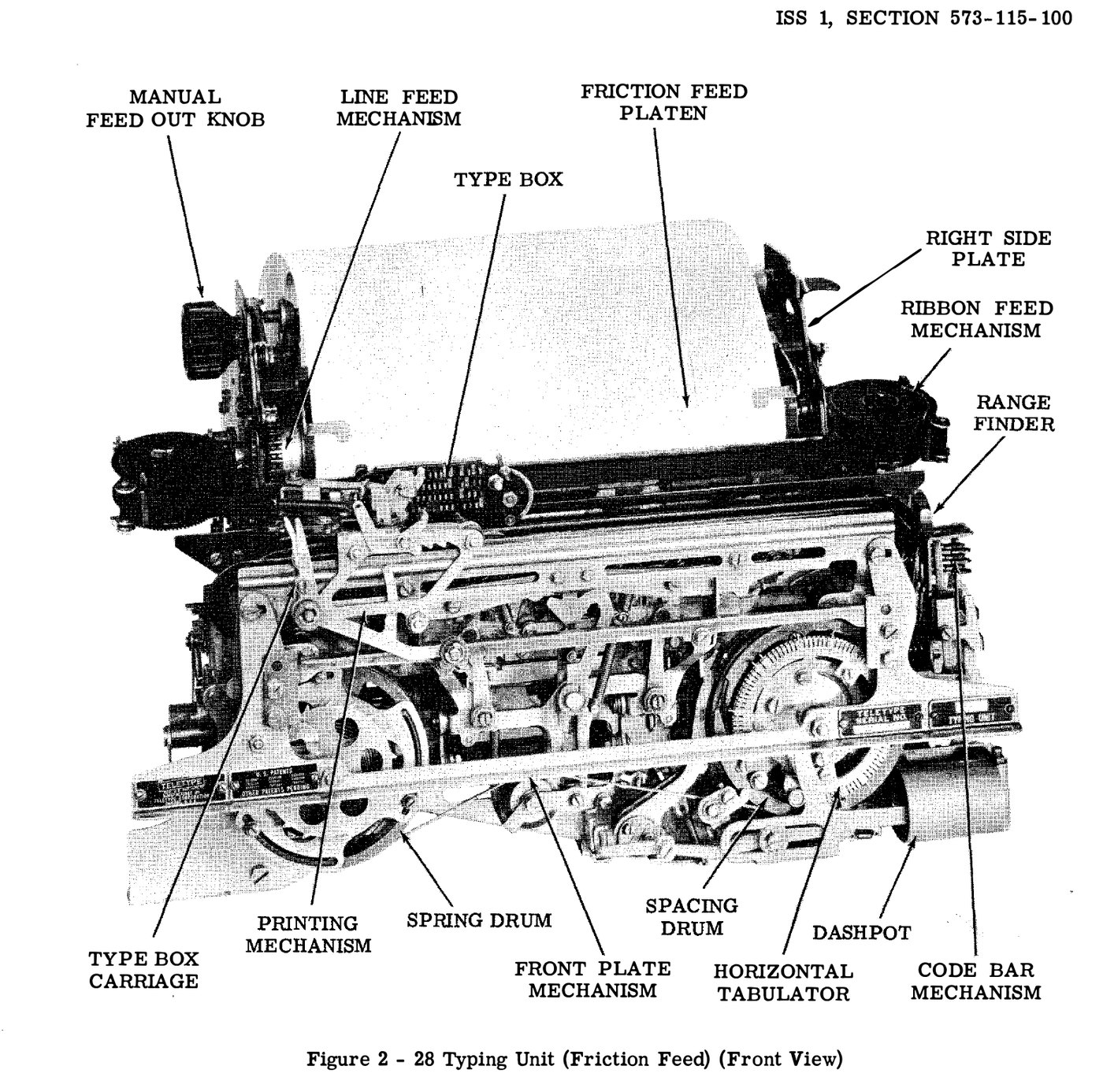
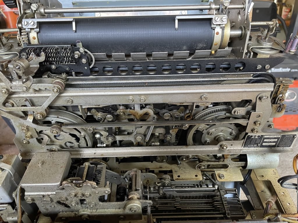
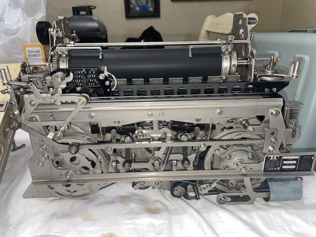
The 28’s typing unit (the LP) is a self-contained module that lifts off its base. Section 573-115-100 gives its size as 15¼ inches wide, 10 inches deep and 9¾ inches high, and its weight as 19 pounds with friction feed or 22 pounds with sprocket feed. It takes its power from the base or keyboard through gears, and its signal input through a plug-in cable from the electrical service unit. Underneath it, the base supports the motor and, on a KSR, the keyboard.
2.3 Power: one shaft, six clutches
2.3.1 The main shaft
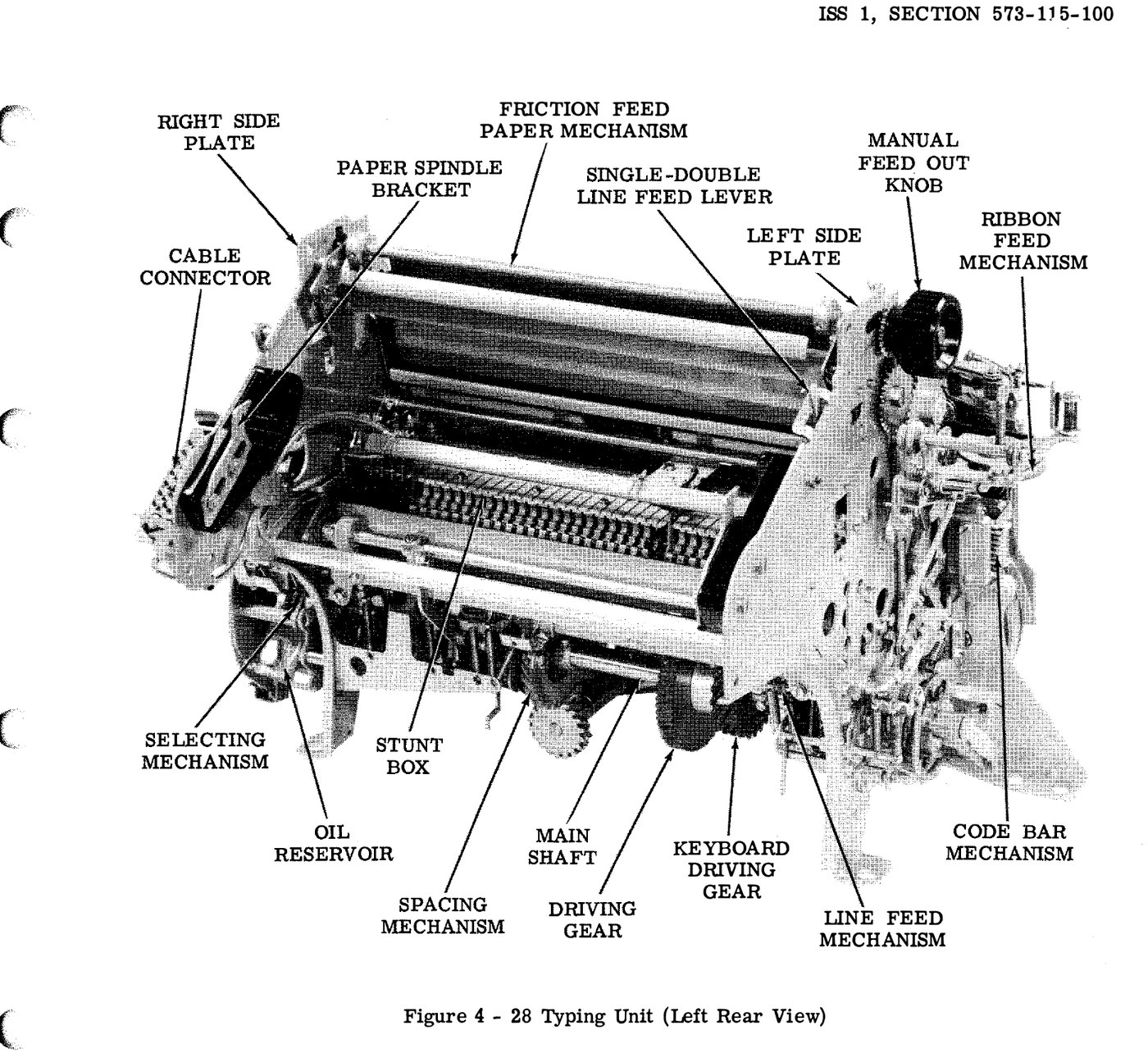
Bulletin 216B places the main shaft in “the lower rear portion of the Typing Unit,” running its full length on ball bearings in the side frames. It turns continuously while the motor runs. When the typing unit sits on a keyboard, a helical gear on the main shaft meshes with the keyboard’s intermediate shaft, which the motor drives, and a second helical gear drives the keyboard’s signal generator. One motor runs everything.
The shaft turns once per character, so its speed is the operating speed: 368 rpm at 60 wpm, 460 at 75, and 600 at 100. The motor speed does not change. What changes is the pair of gears between motor and intermediate shaft, and that gear ratio “determines the maximum speed (operations per minute) at which the equipment will operate” (216B). Changing speed means changing that gear pair (Volume 7).
The intermediate shaft also carries an overload clutch, a safety feature the Model 15 does not have. If the typing unit or keyboard jams, a spring lever jumps out of its notch in the driving gear and the drive stops. Bulletin 216B notes that “the clacking sound made by the overload clutch lever as it strikes its notch with each revolution of the intermediate shaft serves as an audible alarm.” To reset it, switch off and turn the motor by hand until the lever drops back into its notch. If the jam is still there, it will trip again as soon as power returns. That clacking is often the first symptom a new owner hears on a seized machine (Volume 6).
2.3.2 Six clutches, each turning only when tripped
Instead of driving every mechanism from the main shaft all the time, the 28 gives each mechanism its own clutch. Each clutch has a drum keyed to the shaft, so the drum always turns. Inside it are two steel shoes. In the disengaged position the shoes are held together and clear of the drum, so the cam the clutch drives stays still. When a trip lever releases the clutch, a lever spreads the shoes against the drum. Bulletin 216B describes how the drum’s drag on the first shoe pushes it into the second, and how “the forces involved are multiplied at each of the preceding steps, [so] the final force developed … is very great.” The clutch locks to the drum and turns its cam until a stop lug meets the trip lever again, and a latch lever drops into a notch to hold the cam still.
This is the all-steel internal-expanding clutch that The Teletype Story promoted as needing oil only “once or twice a year.” It is the same idea that Western Union later wanted in the Model 32 and 33.
The clutches differ in how far they turn when tripped, set by the number of stop lugs:
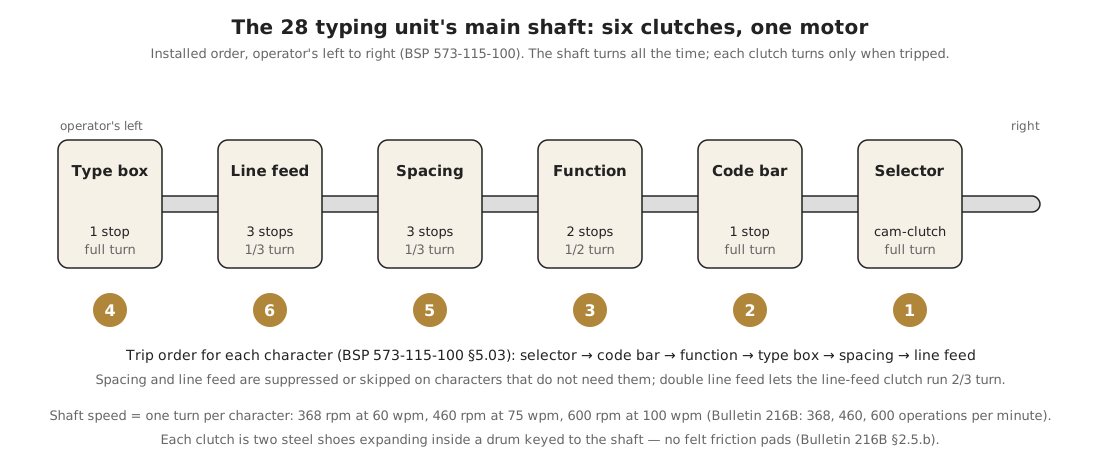
Table 1 — Six clutches, each turning only when tripped
| Clutch (operator’s left to right) | Stops | Turns per trip | Drives |
|---|---|---|---|
| Type box | 1 | full | The main rocker shaft and main bail: vertical and horizontal positioning of the type box, the printing track, the ribbon |
| Line feed | 3 | ⅓ (⅔ for double line feed) | The platen line-feed gears |
| Spacing | 3 | ⅓ | The spacing shaft and drum |
| Function | 2 | ½ | The function (stunt box) reset bail |
| Code bar | 1 | full | The code bar shift levers |
| Selector | cam-clutch | full | The selector cam sleeve |
Section 573-115-100 gives the order in which they trip on each character: “selector, code bar, function, type box, spacing and line feed.” The spacing clutch is skipped when spacing is suppressed, and the line feed clutch runs only on a line-feed code. With nothing on the line, all six are latched and the motor is only turning drums. Bulletin 216B notes that this “reduce[s] the motor load to the minimum when idling.” It is one reason the 28 runs cooler and quieter than the 15 when standing by.
2.4 Receiving: the selector
2.4.1 Two coils, one armature
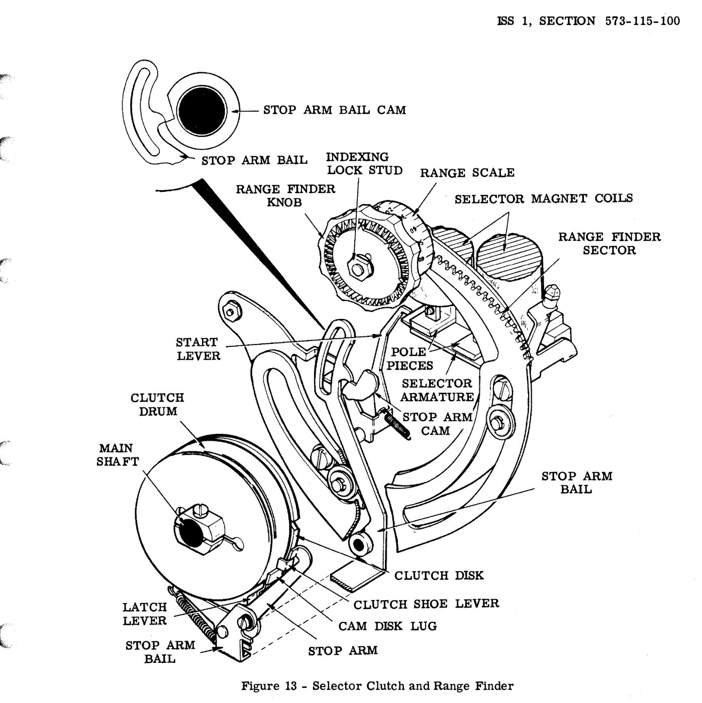
The signal reaches a two-coil selector magnet. In 1953 Bulletin 216B gives the coils as 132 ohms each. They are wired in the electrical service unit, in series for a 20 mA line or in parallel for a 60 mA line (Volume 8). Current through the coils (marking) holds the selector armature against the pole pieces. When the current stops (spacing), the armature spring pulls it away.
Later armatures carry one or two small anti-freeze buttons, which keep a film of oil or residual magnetism from holding the armature to the poles. The adjustment section requires that “the front anti-freeze button must contact the magnet core when the magnet coils are energized,” and that oil is kept out of the gap. Volume 5 covers the second requirement.
2.4.2 Start, sample, stop
At rest the armature, held up by the marking line, blocks a start lever. When the start element arrives, the armature drops, the start lever turns under its spring, and it pulls the stop arm bail into a dip in its cam. That swings the stop arm out of the way of the selector clutch’s shoe lever, and the selector cam-clutch engages. Its cam immediately lifts the stop arm bail and holds it there for the rest of the character, so the start lever cannot interfere. When the stop element arrives, the armature is pulled up in time to block the start lever again, the stop arm bail cannot fall, and the clutch is stopped and latched until the next start element.
This is the same start-stop logic as the Model 15, but done with a clutch, not the Model 15’s friction-driven cam sleeve. A clutch that stops exactly where it should and then latches gives the 28 a definite rest position for every character. That rest position is what the range finder moves (below).
The cam-clutch carries, from right to left (216B): “the clutch, the stop arm bail cam, the fifth, the fourth, and the third selector lever cams, the cams for the spacing and the marking lock levers, the second and the first selector lever cams, the push lever reset bail cam, and the code bar clutch trip cam.”
2.4.3 Locking the armature at mid-element
Two levers on their own cams, the marking lock lever and the spacing lock lever, swing in at each sampling instant. Whichever one the armature does not block locks the armature in its current position “until the next signal transition is due” (216B). This is the 28’s version of the Model 15’s locking cam. It holds the decision steady through the moment of sampling, so a noisy edge cannot change it.
2.4.4 Five selecting levers, five push levers
Five selecting levers follow cams 1 to 5. On a marking element the marking lock lever leaves them free, and the lever opposite the dip in its cam swings into the dip; a push lever drops into a notch on top of it. As the cam turns, the selecting lever carries its latched push lever forward and holds it there. On a spacing element the selecting levers are blocked and their push levers stay back. When the character is complete, “all selected push levers have been positioned to the front and all unselected push levers … to the rear” (216B), and they stay there until the next start element, when a reset bail releases them.
That is the 28’s five-bit storage register: five push levers, forward or back.
2.4.5 Orientation and the range finder
Exactly when in each element the selector samples is set by where the cam-clutch stops. The range finder changes that. Pushing in and turning the range finder knob moves a toothed sector, which carries the stop arm bail, the stop arm and the latch lever, around the cam-clutch. That changes the angle at which the clutch stops, and so every sampling point. When the knob is released, its inner teeth lock on an indexing stud, and the setting can be read on a range scale of 0 to 120 points. Bulletin 216B calls this orientation, and Volume 6 explains how to use it to measure a machine’s health.
2.5 From register to code bars
The push levers do not position the code bars directly. Each push lever acts through an intermediate arm and a transfer lever on a code bar shift bar, which moves to the front (spacing) or rear (marking) of the unit. There is also a sixth, common transfer lever, which moves to the marking position if either bit 1 or bit 2 is marking. The type box section below shows why that is needed.
When the selector cam-clutch nears the end of its turn, its last cam trips the code bar clutch. That clutch swings the front and rear code bar shift levers, which push each shift bar’s code bar right (spacing) or left (marking). A detent holds the bars there. The code bars now spell out the character mechanically, and the selector is free to read the next character while this one is printed.
Bulletin 216B lists nine code bars, top to bottom: suppression, 4, 1, 5, 2, 3, common, automatic carriage return and line feed, and shift-unshift. Five carry the bits. The common bar carries “bit 1 or bit 2.” The suppression bar blocks the type box’s vertical motion in one case (below). The other two are moved by the function mechanism, not the selector.
2.6 Printing: sixty-four pallets, one hammer
2.6.1 The type box
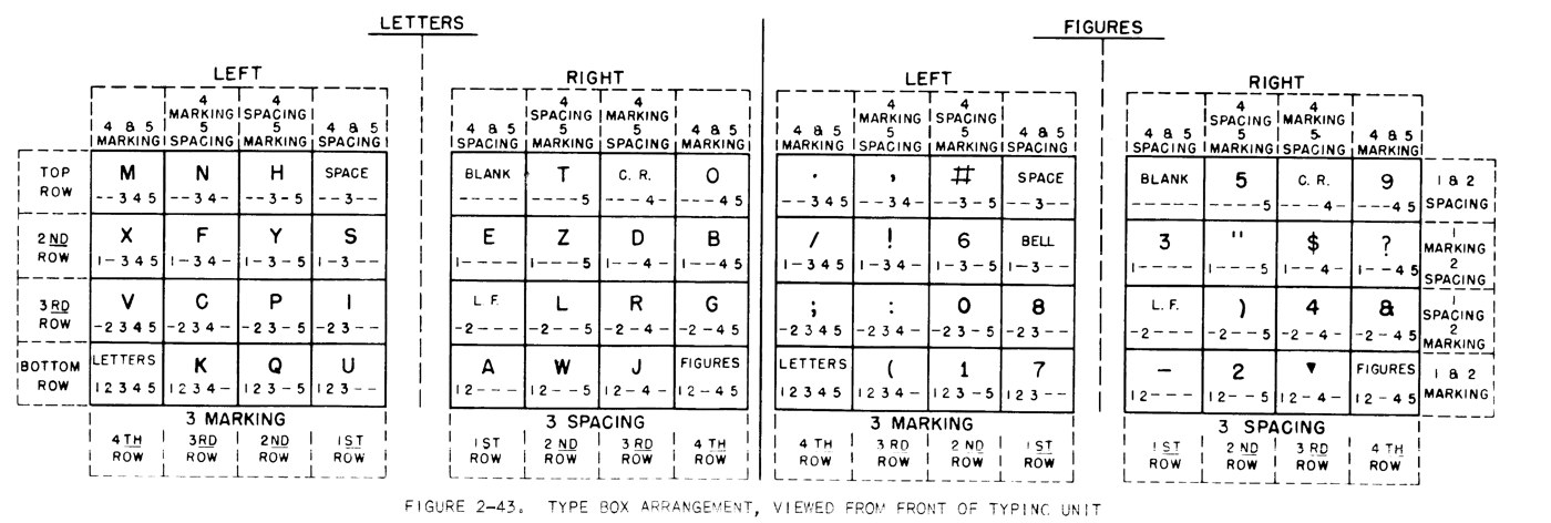
All the 28’s characters are embossed on small steel type pallets held in a removable type box. The Teletype Story gives its size as about 1 × 3 inches. Bulletin 216B says the pallets are “arranged in four horizontal rows and sixteen vertical rows.” That makes 64 positions: 32 on the left for the LETTERS case and 32 on the right for FIGURES. The box rides on rollers in a carriage, and a ribbon guide on the back of the carriage keeps the inked ribbon over the paper.
The type box lifts out without tools, so a single machine can be changed between character sets by swapping a part that fits in a shirt pocket. Wikipedia, citing parts bulletin 1149B, lists sixteen standard type boxes. They include the communications arrangement shown below, weather-symbol boxes for the weather networks (the Navy’s AN/UGC-38 is a weather-symbol RO), and boxes for other alphabets.
2.6.2 How five bits choose a pallet
Bulletin 216B explains the positioning in three steps, and its figure confirms them.
- Row (vertical). When the type box clutch turns, it rocks the main rocker shaft, which drives a pair of main side levers upward. These push hinged “knee action” vertical positioning levers up until they hit whichever code bar is sticking out, and buckle. The type box carriage track rides between those levers, so the bar that stops them decides how high the box rises. Bits 1 and 2 decide which bar that is. Both spacing: the common bar is spacing and stops the levers at the top row. Bit 1 marking, bit 2 spacing: bar 2 stops them, second row. Bit 1 spacing, bit 2 marking: bar 1 stops them, third row. Both marking: only the suppression bar is left to stop them, bottom row. This is the reason the common bar exists. It lets two bits produce four stopping heights with a single set of levers.
- Half (horizontal, coarse). The box moves horizontally on an oscillating rail, driven by an oscillating rail shift slide with buckling drive links at each end. Bit 3 sets a reversing slide that buckles one set of links, so when the main bail comes down the slide moves one way. Bit 3 marking sends the selection into the left four columns of the current case, and bit 3 spacing into the right four columns.
- Column (horizontal, fine). Bits 4 and 5 set three horizontal motion stop slides of different lengths. The shift slide travels until it hits the first unselected stop. Counting outward from the centre of the case, both spacing gives the first column, bit 5 alone the second, bit 4 alone the third, and both marking the fourth.
The case itself (LETTERS or FIGURES) is held by the shift mechanism: a pair of oscillating-rail shift links, one of which is “broken” by the LTRS or FIGS function so that the whole rail sits to one side or the other.
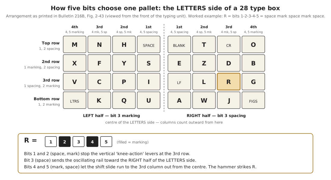
Checking R against the figure: R is space-mark-space-mark-space. Bits 1 and 2 (space, mark) give the third row. Bit 3 (space) gives the right half. Bits 4 and 5 (mark, space) give the third column from the centre. Section 573-115-100 uses R and Y as its own worked example (its Figure 7). Y (mark, space, mark, space, mark) lands in the second row, left half, second column. In both cases the figure agrees with the text.
This is a two-dimensional mechanical decoder, comparable to the Model 15’s single bank of pull bars, but it moves a printing element of about half a pound instead of choosing one of many type bars. That is why the 28 could run faster.
2.6.3 The hammer
Once the box is in position, it is locked by lock levers at the chosen height and by a wedge-shaped horizontal positioning lock lever. The printing carriage, which runs on its own track along the front of the unit, carries a spring-loaded printing hammer. A printing track on the main bail moves a printing arm on the carriage. On the downstroke the arm cocks the hammer and latches it. At the end of the stroke it trips the latch and the hammer springs forward, overshooting its bail “until the printing hammer strikes the selected type pallet” (216B). The hammer hits the pallet, which presses the ribbon onto the paper on the platen.
If the character is a function, not a printing character, the type box is positioned so that the hammer strikes “where there is no type pallet” (216B). That is how the 28 avoids printing on CR, LF, LTRS and FIGS.
After each character the type box and ribbon drop below the line just printed, so the operator can read it.
2.7 Spacing, carriage return and the dashpot
The type box carriage and printing carriage are each clamped to an upper draw wire rope. It runs from a spacing drum on the right, over pulleys, to a spring drum on the left, whose torsion spring constantly pulls both carriages toward the left margin. A lower draw wire rope holds the two drums in step, and a tension pulley takes up stretch.
The spacing drum has ratchet teeth around its edge. Each time the spacing clutch makes its third of a turn, it turns the spacing shaft through a 1½:1 gear pair by half a turn, and eccentric feed pawls advance the drum one tooth: one character space to the right. Some teeth are left off the drum to stop spacing past the margin. Bulletin 216B gives “the maximum number of characters which the Typing Unit may print in one line” as eighty-five. On units with a margin indicator, a cam disk on the spring drum lights a lamp near the end of the line.
On a carriage return, the CR function lever lifts the feed pawls off the drum and latches them up. The spring drum then pulls both carriages back to the left. Near the end of their travel a roller pushes a piston into an air dashpot. Bulletin 216B describes the dashpot’s ball valve, which automatically adjusts the cushioning to the length of the line returned, so a short return and a full 85-character return both stop gently. At the end of the stroke the latch releases and the pawls re-engage. A restorer with a 28 KSR puts the return at “in the time it takes to decode the next received character — about 160 ms” (kb8ojh.net). That speed is why the 28 can do a return and the next character without the fill characters older machines needed.
Combined automatic carriage return and line feed, fitted to many units, makes the machine return and feed a line by itself when the box reaches the right margin, “should the carriage return combination not be received in time” (216B).
2.8 Functions: from function box to stunt box
2.8.1 How a function is decoded
Behind the code bars sits a row of spring-loaded function bars. Each one has a set of lugs on its front edge, bent left or right to match a code. When the function clutch trips, it turns half a turn and briefly lets every function bar spring forward against the code bars. Only a bar whose lugs line up with slots in all the code bars can move in. A selected bar latches its function pawl, and as the reset bail pulls the bar back, the pawl turns a function lever, which does the work: lifts the carriage-return latch, trips the line feed clutch, breaks a shift link, suppresses spacing, rings a bell. Near the end of the cycle a stripper blade rises and frees the pawl.
2.8.2 Shift, unshift on space, line feed
A few of these functions are worth knowing as an owner:
- LTRS and FIGS move the shift-unshift code bar through a fork, and the main bail then breaks one of the oscillating-rail shift links, which moves the whole rail to the LETTERS or FIGURES side.
- Unshift on space: a function bar that responds to SPACE also operates the LETTERS slide, so a space returns the machine to letters. It was a common feature and helps when a FIGS character is lost to noise, because the next space returns the text to normal. Bulletin 216B notes it can be disabled by turning a screw down over the function pawl. An amateur with garbled figures, or who wants to send groups of figures separated by spaces, should know where that screw is.
- Line feed trips the three-stop line feed clutch, and how long the trip lever is held determines whether it turns one third or two thirds of a turn: single or double spacing, chosen by a lever at the upper left rear.
2.8.3 The stunt box
The 1953 machine has a function box with a fixed set of functions. By the late 1950s Teletype had developed it into the stunt box, and its 1959 brochure explains the name: “In the early days of printing telegraphy, ‘stunts’ was the term applied to nonprinting functions.” The stunt box is a removable aluminium housing at the rear of the typing unit, and the brochure says it “is provided with forty two code slots. Each of these slots will accommodate a function mechanism that is designed to perform a specific function.”
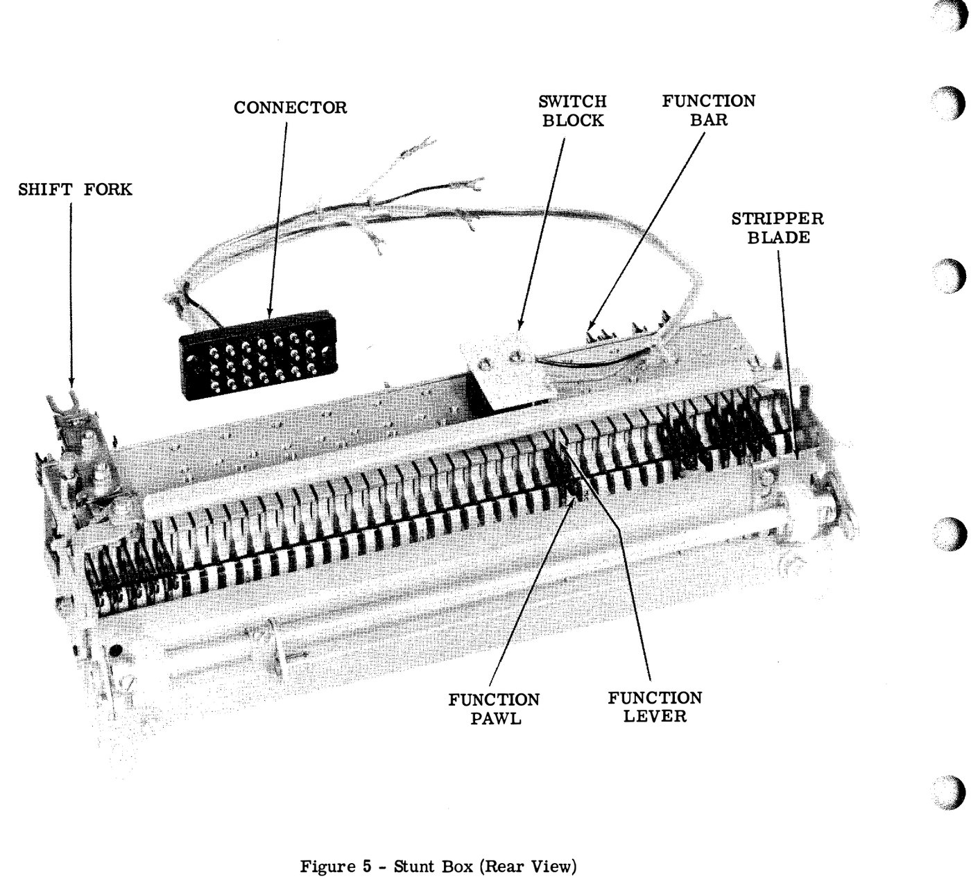
Six slots are normally taken by the basic non-printing functions: letters shift, figures shift, carriage return, line feed, blank, and space suppression on line feed (Teletype, The Stunt Box, 1959). The rest are free. They can hold function mechanisms that operate inside the typing unit (horizontal and vertical tabulation, form feed, reverse line feed, print suppression), switches that operate the set’s own circuits (signal bell, motor stop, starting a tape reader), or switches wired out to external equipment.
What made the stunt box important was sequences. A function bar can be built to respond only after a previous character has set a condition. That lets a 28 recognise a two- or three-letter code, turn on its printer only when its own call letters arrive, print the rest of the message, and lock out again at the end of message. The brochure calls this “a ‘BIG PLUS’ third shift feature,” which reuses the 32 code combinations for control “without ever sacrificing a single printed character.” This is selective calling, and it allowed one circuit to serve many machines that each printed only their own traffic. The 1957 Teletype Story calls the stunt box “a built-in sequential selector,” and suggests it as “a low-cost automatic control instrument” for factories. The brochure gives a lighter example: a programmed stunt box that switches on the office coffee percolator before the staff arrive.
A fully loaded or “universal” function bar has sixteen tines, eight marking and eight spacing. A technician removes the tines that should not be there to code the bar for a particular character. The Stunt Box brochure, scanned and kept on RTTY.COM, is still the clearest explanation of how to set one up, and every 28 owner should read it.
For an amateur the stunt box is less important than it was for a wire service. It handles automatic CR/LF and unshift on space, and some machines arrive with selective-calling bars or answerback triggers fitted. Those can produce strange behaviour (a machine that will not print until it sees a certain sequence, or that locks its keyboard). Volume 6 covers how to recognise that.
2.9 The keyboard and signal generator
On a KSR, the typing unit sits on the keyboard base (the LK). Bulletin 216B describes three banks of keys in the usual typewriter layout, figures and punctuation on the upper case of the same keys, and a fourth row of special keys above them. On many machines those special keys have red tops: BREAK (opens the line), keyboard LOCK and UNLOCK, REPEAT, and local CR and LF that work the typing unit without sending anything.
Pressing a key moves a set of code bars in the keyboard, sets a combination and trips the keyboard’s own clutch. That clutch is driven continuously from the typing unit’s main shaft through a helical gear. The clutch turns the signal generator, a cam assembly that opens and closes a single pair of transmitting contacts in the start-stop pattern for that combination. Those contacts are in series with the line, and so with the typing unit’s own selector magnet. A KSR therefore prints what it sends.
Other parts of the keyboard base:
- A time delay mechanism with two ratchet wheels of 27 and 28 teeth, driven tooth by tooth from the intermediate shaft. Because one has a tooth more than the other, their notches line up only after a fixed number of turns. If no signal has arrived by then, a contact pulses a motor-stop relay in the electrical service unit. Bulletin 216B gives the delay as 86 to 172 seconds at 60 wpm and 53 to 106 seconds at 100 wpm. It is a mechanical idle timer that switches the motor off on a quiet line. It can be disabled by moving a pilot screw.
- A repeat-on-space mechanism on some keyboards, which sends spaces continuously while the space bar is held.
- On some sets, an answerback, a drum of coded tabs that sends a fixed identification when triggered (Inside the Teletype Mechanism, Vol 2, shows one).
A receive-only set uses the LB base instead: the same support for motor and typing unit, with local CR and LF levers and no keyboard.
2.10 The motor
The motor unit (LMU) bolts to the rear of the base. Bulletin 216B describes two kinds:
- Synchronous: “a wound stator, two pole, single phase, capacitor start, motor.” On 60 Hz a two-pole synchronous motor runs at 3,600 rpm, the figure restorers quote. A combined handwheel and fan is on one end of the shaft. The starting relay and capacitor and a thermal cutout switch (“manually reset”) are in a compartment underneath. Because the speed depends on the mains frequency, 216B says the frequency must be held within ±0.75 percent “to avoid loss in receiving margin.” The public grid easily meets that. A small inverter or generator may not.
- Governed: a series-wound motor with a centrifugal governor and fan on the shaft, a speed target painted on the governor cover, and a screwdriver opening for adjustment. It runs from 50 or 60 Hz and is set by eye with a strobe, like the Model 15’s (Inside the Teletype Mechanism, Vol 2).
The synchronous unit is far more common on surplus machines. Volume 6 covers its two usual faults: the thermal cutout trips and has to be reset by hand, and an aged starting capacitor makes the motor rock back and forth instead of starting.
2.11 How the parts fit together
Putting the steps in order for a single received character at 60 wpm, all within one 163-millisecond character time (7.42 units of 22 ms):
- The start element drops the armature, the start lever releases the stop arm, and the selector cam-clutch starts its turn.
- At each element the lock levers hold the armature, the selecting levers sample, and the push levers store bits 1–5.
- Near the end of the turn the code bar clutch trips and sets the nine code bars.
- The function clutch half-turn checks the stunt box. If it finds a function, the function lever acts and the type box is sent to a blank position.
- The type box clutch turns once. The knee-action levers raise the box to its row, the shift slide moves it to its column, and the hammer fires.
- The spacing clutch advances the carriages one space, unless suppressed. The line feed clutch turns only for LF.
- Meanwhile the selector has already started on the next character, because steps 3 to 6 overlap with the next character’s arrival.
That overlap, the selector reading one character while the rest of the unit prints the previous one, is what lets the 28 reach 100 wpm with a light, moving type box.
2.11.1 Sources (Vol 2)
- 🔴 Primary source: Teletype Corporation, Bulletin No. 216B: General Description and Theory of Operation, Model 28 Printer (June 1953), Section 2. Main shaft, ball bearings, the six two-shoe internal-expanding clutches and the force-multiplying shoe action; 3-stop line feed and spacing clutches, 2-stop function clutch; reducing motor load when idle; the intermediate shaft, speed set by the gear pair, the overload clutch and its “clacking” alarm; the two 132-ohm selector coils; start lever, stop arm bail, cam-clutch layout, marking and spacing lock levers, selecting levers and push levers; orientation and the range finder; transfer levers, the common transfer lever and the nine code bars in order; type box rows and columns (Fig. 2-43), knee-action levers, oscillating rail and shift slide, horizontal stop slides; hammer action and printing on a blank position for functions; draw wire ropes, spring and spacing drums, 1½:1 spacing gears, 85 characters per line; dashpot and ball valve; ribbon reversal; function box, function bars, pawls, levers and stripper blade; LTRS/FIGS shift links; unshift on space and the screw that disables it; single and double line feed; keyboard layout and special keys; time delay mechanism (27- and 28-tooth ratchets; 86–172 s at 60 wpm); synchronous and governed motors; ±0.75% frequency. https://bitsavers.org/communications/teletype/28/216B_Model28_Descr_Jun53.pdf
- Typing unit dimensions and weights (19 lb friction feed, 22 lb sprocket); clutch order and trip sequence (§5.03); 3-stop and 1-stop clutches; anti-freeze buttons; Figs. 2, 4, 5, 13. Teletype Corporation, BSP 573-115-100, 28 Typing Unit, Description and Principles of Operation, and BSP 573-115-700, Adjustments, Issue 7, in Technical Manual, 28 KSR and RO Teletypewriter Sets, NAVSHIPS 0967-173-7010 (Bulletin 311B, Vol 1, July 1967). https://www.navy-radio.com/manuals/tty/0967-173-7010-6707.pdf
- Stunt box: the name, 42 code slots, the six standard functions, sequences and selective calling, the “third shift,” the universal function bar with sixteen tines, the coffee-percolator example. Teletype Corporation, The Stunt Box (1959), at RTTY.COM. https://rtty.internet-tty.net/downloads/stuntbox.pdf
- Type box about 1 × 3 inches; the stunt box as “a built-in sequential selector” and “a low-cost automatic control instrument.” Teletype Corporation, The Teletype Story (1957). https://rtty.internet-tty.net/downloads/teletype-story.pdf
- 3,600 rpm motor; carriage return in about 160 ms; type box travel. kb8ojh.net, “Teletype Model 28 KSR.” https://kb8ojh.net/station/teletype/
- Sixteen type boxes listed in parts bulletin 1149B. Wikipedia, “Teletype Model 28,” citing Teletype Bulletin 1149B (1963). https://en.wikipedia.org/wiki/Teletype_Model_28 ⟨1149B is staged for the Library⟩
- AN/UGC-38 as the weather-symbol version of the compact RO. navy-radio.com, “US Navy Teletype Equipment.” https://www.navy-radio.com/tty.htm
- Typing unit photographs. David Stickelman, “Teletype Model 28 Gets a Bath” and “Digging into the Teletype Model 28 Wall Mount” (September 2024). http://stickelman.net/index.php/2024/09/11/teletype-model-28-gets-a-bath/
- Cross-links: Inside the Teletype Mechanism (the Model 15 selector and the 8:7 ratio; the answerback drum; the governed motor and strobe); Teletype Machines (the start-stop frame and LTRS/FIGS); The Teletype Model 15 (https://dots-and-dashes.fubsypoly.com/teletype-model-15/).