The Teletype Model 28 · Volume 4
The Teletype Model 28 — Vol 4: Tape on the 28 — Punches, Readers and the ASR
The 28 family includes four kinds of tape punch, a set of transmitter-distributors, reperforator-transmitters for relay centres, and the ASR that combines them with a page printer. This volume covers what each one does, how the ASR's mode switch routes the signal, and how tape from a 28 gets in and out of a computer.
4.1 Why tape mattered
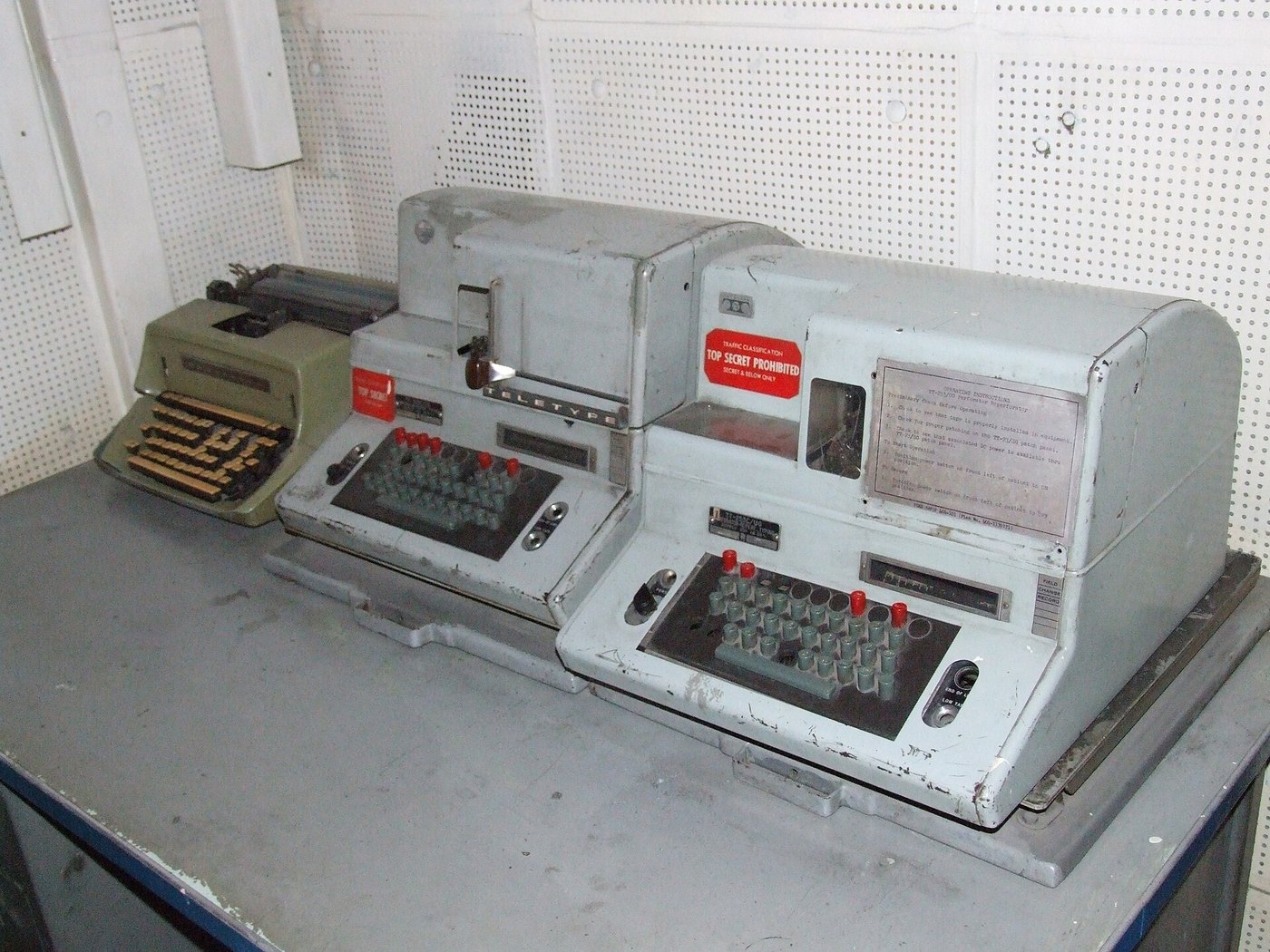
Paper Tape and the Perforator covers five-level tape in general: what the holes mean, how to read them by hand, why tape mattered for store-and-forward traffic. The pink tape I remember coming out of the punch in my father’s shack was five-level tape, eleven-sixteenths of an inch wide. This volume is about the 28 family’s tape equipment specifically, which was the most complete Teletype ever offered for five-level work.
The reasons for putting a message on tape were the same in 1957 as they had been in the 1930s. An operator can type a message off-line at their own pace, correct it, and then send it at full line speed without pauses. A message received on tape can be sent on to another circuit without retyping. One tape can be sent many times. For the 28 the reason was even stronger, because at 100 wpm nobody types fast enough or steadily enough to keep the line full.
4.2 The tape
The 28’s tape equipment uses standard American five-level tape. The ASR operating instructions say that “any five-level tape 11/16 inch wide and 10-hole-per-inch feed, chadless or fully perforated, typed or blank, can be fed into the transmitter-distributor” (BSP 573-101-100TC). Two code holes lie on one side of the feed holes and three on the other. The operating instructions say “the two code perforations should be toward the back of the transmitter” when tape is loaded.
Tape came in two forms, and both 28 punches and readers handle both:
- Fully perforated: each code hole is punched cleanly and the circle of paper (the chad) drops into a chad box. The tape is easy to read by eye and by any reader.
- Chadless: each code hole is cut only most of the way around, leaving a hinged flap. The tape is stronger and there is no chad to empty, and the space between holes can carry printing. Readers must be adjusted to sense chadless tape correctly.
The tape supply itself is plain paper on most 28 equipment. Older mechanical punches needed oiled tape, impregnated with oil to lubricate the punch pins and dies. Collectors report that equipment from about 1960 onward generally works with plain dry tape, and that oiled tape made to the old specification is hard to find now. Unused old stock does turn up. Buy dry tape for a 28 unless its documents say otherwise. Tape came in colours as well as plain buff, and the pink tape of my memory was one of them.
4.3 The four punches
The 28 ASR manual sorts the punches into two pairs (BSP 573-101-100TC, §3.05–3.06):
Table 1 — The 28 ASR manual sorts the punches into two pairs (BSP 573-101-100TC, §3.05–3.06)
| Unit | Driven by | What it produces |
|---|---|---|
| LPE, non-typing perforator | The keyboard, mechanically | Holes only |
| LTPE, typing perforator | The keyboard, mechanically | Holes, and the characters typed along the tape |
| LRPE, non-typing reperforator | Incoming signals, through its own selector | Holes only |
| LPR, typing reperforator | Incoming signals, through its own selector | Holes and printed characters |
A perforator is built into the ASR keyboard base and punches whatever the operator types. A reperforator (“re-perforator,” because it re-creates a tape at the far end of a line) has its own selector magnet and responds to the signal on its line, exactly like a typing unit. The reperforators “may also be actuated mechanically” when mounted where a keyboard can drive them.
4.3.1 The LPR typing reperforator
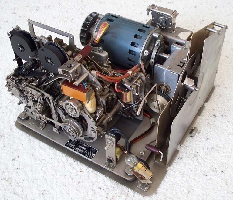
The LPR is the 28 tape unit most often found on its own, as a KTR, ROTR or RT set. Unlike the page printer it does not use a type box. Teletype’s description section says “the characters used in printing are embossed on a bakelite typewheel.” It prints the text on the tape itself, so a relay operator can read a message by looking at the tape:
Table 2 — The LPR is the 28 tape unit most often found on its own, as a KTR, ROTR or RT set. Unlike the page printer it does not use a type box. Teletype's description section says "the characters used in printing are embossed on a bakelite typewheel." It prints the text on the tape itself, so a relay operator can read a message by looking at the tape
| LPR tape specification (Bulletin 246B, BSP 573-102-100) | |
|---|---|
| Tape width | 11/16 inch |
| Perforations | Five-level, chadless or fully perforated |
| Holes per inch | 10 |
| Printed characters, chadless | 0.120 in high, 0.075 in wide (standard) |
| Printed characters, fully perforated | 0.100 in high, 0.046 in wide |
| Where it prints | Along the upper edge of chadless tape; between the feed holes on fully perforated tape |
A fully perforated tape has no room left at the edge, so the LPR prints its smaller characters in the line of the feed holes. On chadless tape, the code holes are not punched out, which leaves room for bigger characters along the edge. The sets ran “at various speeds up to 100 words per minute” with interchangeable gears, and some receive-only sets had “an optional, variable speed drive mechanism” in place of fixed gears (573-102-100).
4.4 The transmitter-distributors
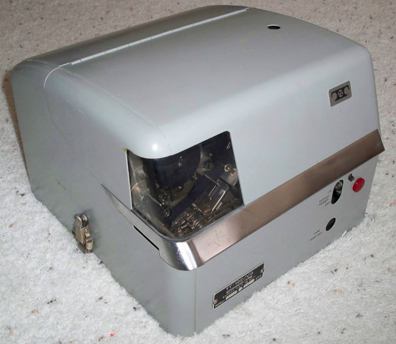
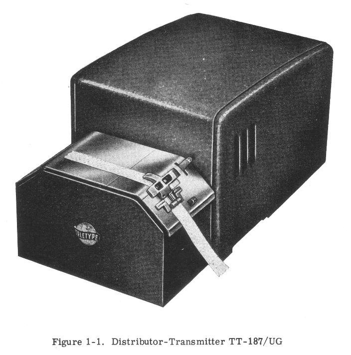
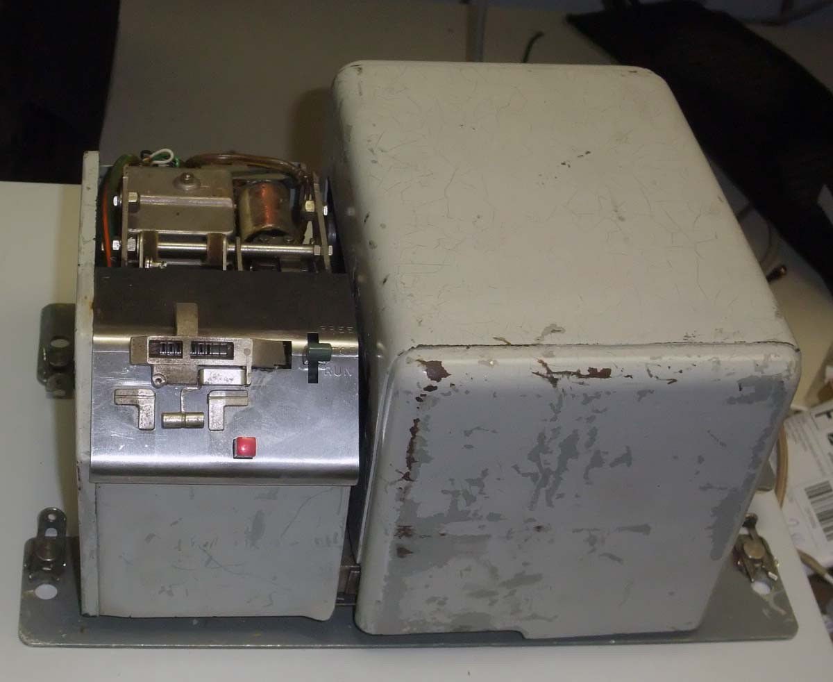
A transmitter-distributor (TD) feeds tape past a reading head and sends what it reads onto the line as start-stop signals. The name comes from its two halves: the transmitter reads the five holes in parallel, and the distributor sends them out one after another with start and stop elements. The ASR manual lists four kinds the ASR can use (BSP 573-101-100TC, §3.08), under codes from the LXD family:
- Fixed head, single contact. A fixed reading head and a single-contact distributor; serial output. This is the ordinary TD.
- Pivoted head, multicontact. The reading head can move along the tape so it reads “the last character punched,” directly behind the punch. “This unit is used frequently with continuous tape loops.” Output can be serial or parallel.
- Fixed head, multicontact. Reading head and distributor can be controlled separately, locally or remotely. Output serial or parallel, and “the signal distributor also accepts external parallel inputs and converts them to serial form.”
- Pivoted and fixed head, multicontact. Two reading heads, one following the punch and one for tapes loaded by hand, sharing one distributor, “to combine inputs, such as standard and variable data.”
The codes LXD, LAXD, LBXD and LCXD belong to these designs, plus the separate LX reader used as a second head. The ASR installation section names them without a one-to-one key, but the bulletin titles help: Bulletin 252B, for example, is the technical manual for the “28 Transmitter Distributors (Pivoted and Fixed Head Multicontact) (LAXD, LCXD).” Match a unit’s code to its own section before adjusting it.
4.4.1 Loading and running a tape
The ASR operating instructions give the procedure (BSP 573-101-100TC, §3):
- With the TD’s three-position start-stop switch off, press the red button to lift the spring-loaded tape lid.
- Lay the tape on the teeth of the feed wheel with the first character to be sent “directly over the sensing pins,” two code holes toward the back. Hold it flat and close the lid.
- Start the TD with its switch. It sends at line speed until it runs out of tape, or until the tight-tape or tape-out lever stops it. These stop it automatically if the tape snags or ends.
- To stop and insert a correction or another message, raise the switch to its intermediate position, note where the tape is against “the index line scored in the tape guides,” take the tape out, and put the other tape in. Afterwards, put the original back where it was stopped.
- To feed a leader of tape by hand, raise the switch to its upper, free-wheeling position.
On an ASR, the TD only sends when the mode switch is in T or K-T with the send key pressed.
4.5 The ASR: one cabinet, three ways of working
4.5.1 What is in the cabinet
A 28 ASR combines (BSP 573-101-200TC, Fig. 2):
- A page printer (the LP typing unit, on the right).
- A keyboard perforator-transmitter: the LAK keyboard and a perforator (LPE or LTPE) or a reperforator (LRPE or LPR), in the middle.
- A TD on its own LCXB base, on the left, driven from the keyboard’s motor.
- One motor (LMU) driving the keyboard, punch, typing unit and TD, which run in step.
- An electrical service unit with the power switch, terminal blocks, fuses and any line relay.
- Optionally, an auxiliary typing reperforator (LPR on an LRB base) with its own motor and ESU, in the cabinet behind the TD. The ASR manual says some of these have a variable speed gearshift “for 60, 75, or 100 word per minute speeds.”
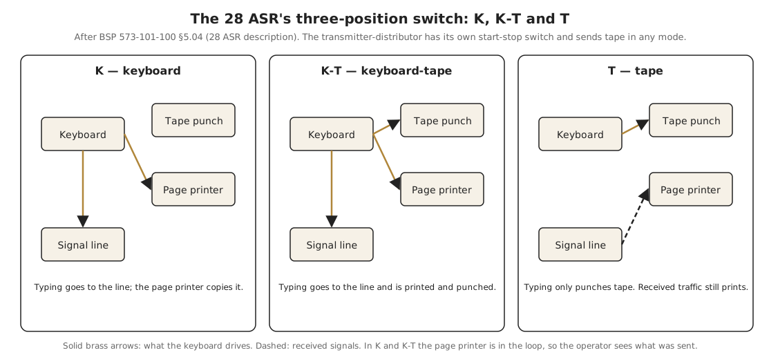
4.5.2 The mode switch: K, K-T, T
A three-position mode selector switch on the front panel decides what the keyboard does (BSP 573-101-100TC, §5.04):
- K (keyboard). The keyboard sends to the line, and the page printer prints what is sent. The punch is idle.
- K-T (keyboard-tape). The keyboard sends to the line and also punches tape, so “all transmission [is recorded] in both punched tape and page-printed form.”
- T (tape). The keyboard only punches tape. Nothing is sent. The page printer stays on the line and prints anything received.
4.5.3 A day’s work on an ASR
These modes support a typical message-centre working pattern:
- In T, the operator types outgoing messages onto tape, at their own pace and correcting mistakes, while incoming traffic prints on the page. The LTPE or LPR’s printing on the tape shows what has been typed. A mistake is corrected by backspacing the tape and overpunching the wrong character with LTRS, which has all five holes punched and which every machine ignores (the ASR’s back-space mechanism exists for exactly that).
- With a tape ready, the operator loads it in the TD and sends it at full line speed. The page printer prints it as it goes out, as a check.
- Received traffic for relay arrives on the auxiliary reperforator as tape, which can be torn off and put straight into the TD to go out on another circuit.
That third step is torn-tape relay, and it was the main work of the military and commercial message centres of the 1950s and ’60s. Teletype built entire systems around it: the “28 Universal Torn Tape System” and the “28 Torn Tape System” each have their own three-volume manual (Bulletins 275B and 326B) on navy-radio.com. RT sets and multiple ROTR cabinets were their building blocks. Later “automatic” relay centres replaced the person tearing tape with stunt-box and switching control.
4.5.4 Tape for amateurs
For amateurs, the ASR’s attraction was obvious. Tape meant pre-typed CQ calls and station descriptions, perfectly timed transmission, the test tapes of “RYRY” and “THE QUICK BROWN FOX” that every RTTY station needed, and the ability to send RTTY art (Volume 1) built up line by line on tape. The pivoted-head TD, which can read right behind the punch, could also let an operator type into the punch and have the TD send each character a moment later at an even rhythm, a practical form of type-ahead.
4.6 Getting tape into and out of a computer
The general methods of connecting a teletype’s loop to a computer are in Interfacing Teletypes and Paper Tape. A few points are specific to the 28’s tape equipment:
- The code is five-level Baudot (ITA2/US-TTY), with LTRS and FIGS shifts. A computer reading 28 tape has to track the shift state and convert to ASCII. A tape punched on an ASR is the same code that went on the line, including CR, LF, LTRS and blank characters.
- The easiest path is serial. A 28 TD sends a standard start-stop loop signal at the speed of its gears. Through a loop interface, a computer sees a TD as a serial port at 45.45, 56.9 or 74.2 baud (60, 75 or 100 wpm). For a 1950s machine this is a remarkably clean way to read a pile of old tapes: the TD does the mechanical work, and the computer only decodes.
- Some TDs and the LRS have parallel outputs. The multicontact TDs and the LX reader can present five wires in parallel, and the LRS receiving selector converts a serial line to parallel wires with no printer at all. These were designed for exactly the kind of machine control and data processing that The Teletype Story promoted. They are useful today too, but each needs its own wiring diagram.
- Punching from a computer is the reverse: send serial Baudot into a reperforator’s loop. An ROTR or the ASR’s auxiliary LPR punches whatever arrives, at the speed of its gears. The LARP multi-magnet reperforator takes parallel input instead.
- Old tapes can be read without a 28. Optical tape readers and the methods in Paper Tape and the Perforator work on any five-level tape. That is the safer route for fragile or one-of-a-kind tapes, because a mechanical TD’s feed wheel and pins can tear old, brittle paper.
4.6.1 Sources (Vol 4)
- 🔴 Primary source: Teletype Corporation, BSP 573-101-100TC, 28 Automatic Send-Receive (ASR) Teletypewriter Sets — Description and Principles of Operation (§3.05–3.08 perforators, reperforators and the four TD designs; §5.01–5.05 operation, the K/K-T/T mode switch, tight-tape and tape-out stops; auxiliary typing reperforator with gearshift for 60, 75 or 100 wpm), and BSP 573-101-200TC, Installation (Fig. 2, location of units; LAK/LPE, LTPE, LRPE or LPR; LAXD, LBXD, LCXD, LXD or LX; LCXB; LRB; LAAC), with the operating instructions (§3.01–3.03, tape 11/16 inch and 10 holes per inch, loading on the feed wheel with two code holes toward the back, the index line, the three-position TD switch). In Technical Manual, 28 ASR Teletypewriter Sets, NAVSHIPS 0967-173-6010 (Bulletin 312B, Vol 1, July 1967). https://www.navy-radio.com/manuals/tty/312b-v1-orig-6707.pdf
- LPR typing reperforator: bakelite typewheel; tape specification; character sizes and position on chadless and fully perforated tape; KTR, ROTR, miniaturized and multiple sets; variable speed drive. Teletype Corporation, BSP 573-102-100TC and 573-118-100TC, in Bulletin 246B, Description and Principles of Operation, Model 28 Typing Reperforator Sets (1964). https://www.navy-radio.com/manuals/tty/246B-6402.pdf
- LAXD and LCXD (pivoted and fixed head multicontact TDs). Teletype Corporation, Bulletin 252B, Technical Manual, 28 Transmitter Distributors (Pivoted and Fixed Head Multicontact) (LAXD, LCXD) (cover title). https://www.navy-radio.com/manuals/tty/252b.pdf
- Torn tape systems (Bulletins 271B, 275B, 326B) and the Navy ROTR, KTR and TD sets (TT-192, TT-253, TT-187). navy-radio.com, “Manuals — TTY” and “US Navy Teletype Equipment.” https://www.navy-radio.com/manuals-tty.htm · https://www.navy-radio.com/tty.htm
- Oiled tape for older punches and plain tape after about 1960; difficulty of making oiled tape to specification. cctalk / classiccmp.org discussion of paper tape supplies (summarised from the thread). https://classiccmp.org/mailman3/hyperkitty/list/[email protected]/message/LVHYUA3VG6YMEABC35ZCL7D7IEJCRHTB/ ⟨treat as collector opinion⟩
- LRS receiving selector and LARP; the stunt box and data processing. Wikipedia, “Teletype Model 28”; Teletype Corporation, The Teletype Story (1957). https://en.wikipedia.org/wiki/Teletype_Model_28
- ROTR, TD and KTR photographs. navy-radio.com; Nicor, “USS Pueblo (AGER-2) 07,” Wikimedia Commons. https://commons.wikimedia.org/wiki/File:USS_Pueblo_(AGER-2)_07.jpg
- Cross-links: Paper Tape and the Perforator (five-level tape, chad, reading by hand); Interfacing Teletypes and Paper Tape (https://dots-and-dashes.fubsypoly.com/interfacing-teletypes-and-paper-tape/); RTTY on the Air (RY test tapes); The Teletype Model 15 (the Model 19 and Model 14 tape equipment, https://dots-and-dashes.fubsypoly.com/teletype-model-15/).
