The Teletype Model 15 · Volume 7
The Teletype Model 15 — Vol 7: Tape — the Model 14 Companions and the Model 19
The machines that punched, typed and read the tape around a Model 15: the perforator-transmitter keyboard, the Model 14 typing reperforator, the transmitter-distributor and the Model 19 that combined them, and how the same tape equipment connects to a computer today.
7.1 Why a page printer needed tape
A Model 15 on its own sends exactly as fast as its operator types and receives only while someone at the other end is typing. For a private wire between two offices that was fine. For a message centre handling hundreds of messages a day, a press wire, a weather network or a military communications centre, it was not.
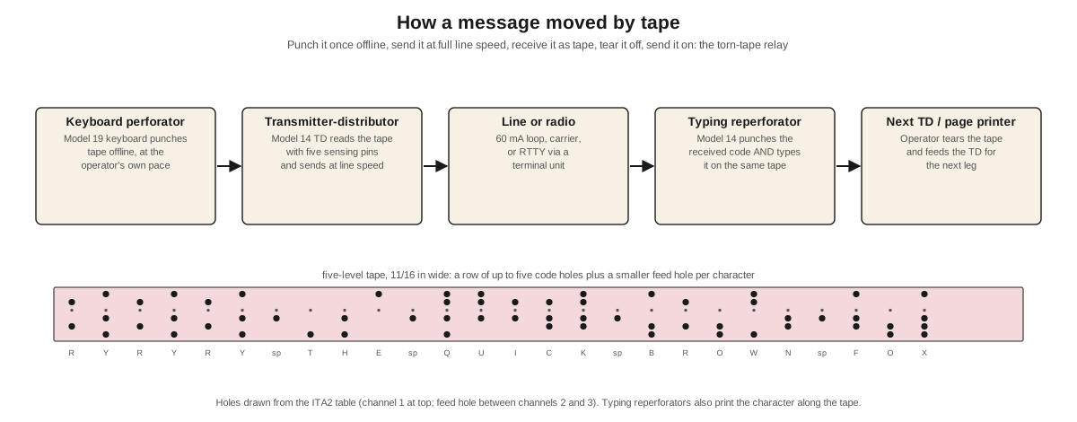
Punched paper tape solved three problems at once. A message could be prepared offline at the operator’s own pace, checked and corrected, and then sent at full line speed, so the expensive line was never idle while someone hunted for a key. A message received as tape could be sent on to other stations without being retyped, which is the basis of the torn-tape relay. And a tape was a record that could be filed, re-sent or sent to several places.
Paper Tape & the Perforator explains the tape itself: the five-level code, the feed hole, chadless and fully punched tape, and how to read the holes by hand. This volume is about the particular machines that worked with the Model 15, which were almost all members of Teletype’s Model 14 family, and about the Model 19, the set that put the Model 15 and its tape equipment on one table.
7.2 The Model 14 family
The Model 14 began in 1925 as a type-bar tape printer: a receiving machine that printed incoming messages on a narrow paper strip, which an operator then cut and pasted onto a telegram form. Teletype’s history records that it reached its highest production in 1929 and 1930 and that about 60,000 had been sold when it was discontinued in the late 1950s; a separate Model 14 tape punch, first marketed in 1941, sold about 50,000 (House 2001).
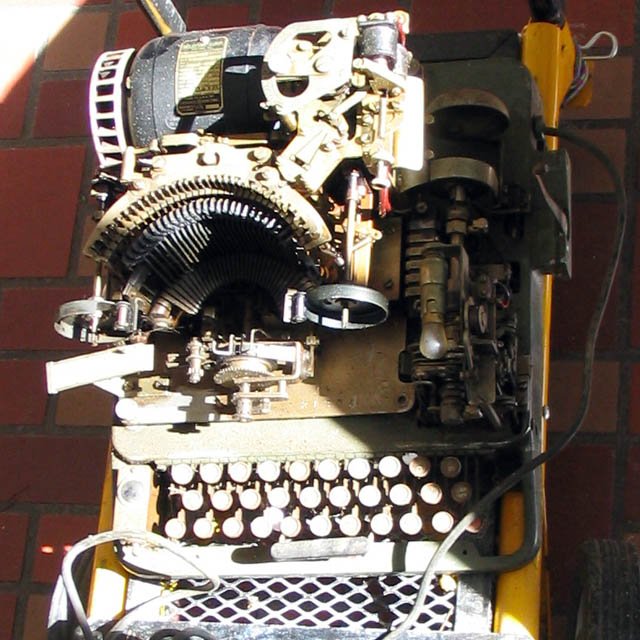
Over the years “Model 14” came to cover a family of machines sharing the same mechanical ideas as the Model 15: the same selector, the same five-unit code, the same motors and gears. Teletype’s 1948 equipment list has sections for Model 14 perforator sets, nontyping reperforator sets, typing reperforator sets in receive-only and send-receive forms, and combinations of these with transmitter-distributors (Teletype Equipment List, 1948). S-5321, the 1941 specification for changing a Model 15 between synchronous and governed motors, covers the Model 14 reperforator and transmitter-distributor in the same document, with their own gears (S-5321).
7.3 Punching tape: the perforator-transmitter keyboard
The simplest way to make tape at a Model 15 is to replace its keyboard with a perforator-transmitter keyboard, which punches tape as the operator types and can send to the line at the same time. Teletype’s equipment list offered a “Teletype Model 15 Sending-Receiving Page Printer (with Perforator Transmitter Keyboard) Set,” and the Model 19 is built around the same keyboard (below).
The amateur notes on RTTY.COM describe the swap from the owner’s side: the Model 15’s keyboard “can be replaced with a perforating keyboard, making the unit similar to a Model 19,” but the perforator’s punch magnets need a separate supply, rated at 500 mA at 110 V DC (rtty.com, “Model 15 Teletype”). That supply is far heavier than the 60 mA loop, and its absence is the usual reason a perforator keyboard found with a machine does not punch.
7.4 Receiving tape: the reperforators
A reperforator punches tape from the line instead of from a keyboard. There are two kinds.
The nontyping reperforator punches only the code holes. It is simpler and was used where the tape went straight into another transmitter-distributor without anyone needing to read it.
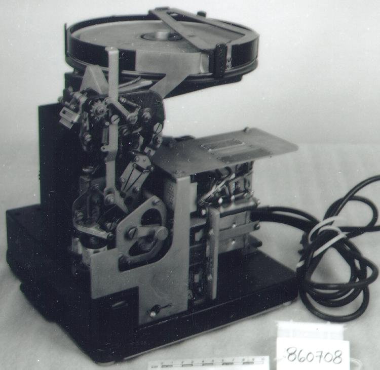
The typing reperforator punches the code and types the character on the same tape. Teletype’s Bulletin 172 (1943) describes it as “a motor driven mechanism for receiving messages over wires and recording the messages in both code perforations and typewritten characters on the same tape.” It uses standard 11/16-inch perforator tape with chadless perforation, in which the chad stays attached as a hinged flap so that the tape surface is left whole enough to print on. Letters are printed near the top of the tape and figures near the bottom (Bulletin 172B). The bulletin explains why it suited message centres: “the perforated tape may be used to retransmit the message to one or more stations by means of … a transmitter-distributor, thus eliminating the necessity for manual transmission,” and “the typewritten characters on the tape facilitate identification and distribution of the message tape at the message center.” With a keyboard transmitter in a local circuit, the same machine also serves as a keyboard perforator.
The bulletin lists the options that a Model 15 owner will recognize, because they are the Model 15’s own: pulling-magnet and holding-magnet selectors, unshift on space, keyboard lockout, a polar-neutral key, a signal line relay, and a mechanical tape-out alarm.
The military named these machines too (JANAP 161): the TT-53/FG is a Model 14 receive-only reperforator “used for production of message tapes which may be distributed later by a transmitter-distributor to line circuits or to local page printers,” and the TT-74/FG a send-receive typing reperforator for “tape-relay and torn-tape switching applications.”
7.5 Sending tape: the transmitter-distributor
The transmitter-distributor, or TD, reads punched tape and sends it to the line. Teletype’s Bulletin 141 describes it as “a motor driven device which translates code combinations, perforated in a paper tape, into electrical impulses and transmits these impulses to one or more receiving stations,” from tape “perforated by any one of several models of Teletype perforating or reperforating machines” (Bulletin 141B).
It works in two halves, as its name says. The transmitter senses the tape: five tape pins rise against each row and either pass through a hole or are stopped by the paper, setting five contact tongues to marking or spacing. The distributor sends them: brushes sweep around a ring of segments at a uniform speed, connecting the start segment, the five code segments and the stop segment to the line in turn. The tape then steps forward one row. Because the distributor’s timing comes from its motor, not from a hand on a keyboard, a TD sends perfectly regular characters at full line speed for as long as there is tape.
Two features matter in practice. A tight-tape stop halts transmission if the tape snags or tangles going into the reader, and an end-of-tape stop halts it when the tape runs out; the 1964 bulletin also describes a stop for a torn feed hole. Teletype made two-channel TDs, and six-unit versions for the Teletypesetter, but the five-unit single-channel TD is the one found with Model 15s.
Speeds. The bulletin notes that at 368 operations per minute the transmitted impulses have a frequency of 23 cycles per second, a reminder of how slow the signal is. A 1954 Teletype sheet for a later Model 14 TD says it was “made to transmit a 7.42 code at 100 w.p.m.” and could run at 60 or 75 wpm with gear changes, or at 65 wpm on a 7.00-unit code (1948 list, sheet 19D5). The Army’s manual for Model 14 TDs, TM 11-2222 (1951), covers the TT-12/FGQ-1, TT-13/FGC-1, TT-21/FG, TT-25/FG, TT-26/FG and TT-52/FG, and gives their tuning-fork frequencies for setting governed motors (Volume 4).
Lubrication. A TD is lubricated by the same rules as the Model 15 (Volume 4). Bulletin 141B gives its motor bearings two drops of KS-7470 oil every four months, and the 1954 sheet says that TDs with the later all-metal clutch need oil only once or twice a year.
7.6 The Model 19: one table, all three jobs
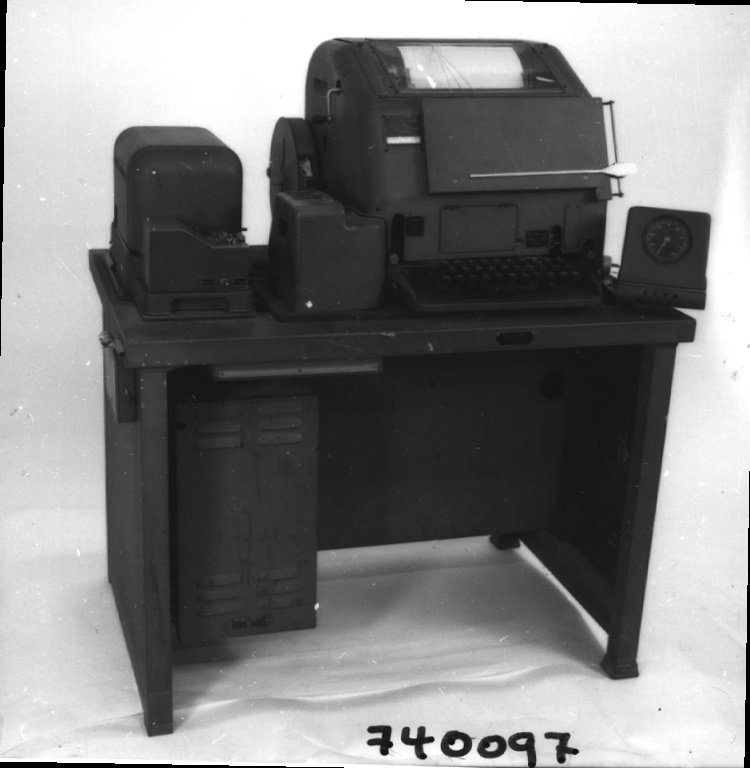
The Model 19 is a Model 15 with its tape equipment built in. Teletype’s 1946 general description sheet lists its parts: a Model 15 page printer with a perforator-transmitter keyboard (with a counting pointer and dial, so the operator can see how far along the line the tape has reached), a Model 14 transmitter-distributor, a table, a rectifier and a speed indicator. The table has room for a Model 14 reperforator underneath at the left front. The set weighed 286 lb net and measured 36 × 23½ × 42 inches (1948 list, sheet 4.D1-1). It could send directly from the keyboard, punch tape with or without sending, and send automatically from tape.
Teletype’s histories disagree about its date. CuriousMarc’s restoration notes, and most lists of Teletype models, give 1940; Teletype’s own synopsis says that Models 19 and 20 were “developed for auto-control of transmission” in 1946–1950 (House 2001). Teletype’s 5MA manual for the Model 19 set is dated September 1942, so the Model 19 existed during the war; the postwar dates probably refer to later development of the line.
The 5MA manual’s list of contents shows what came with a Model 19: Specification S-5288 (lubrication), S-5017 (installation), Bulletin 144 (description of the Model 15), Bulletin 138 (adjustments), Bulletin 1094 (printer parts), Bulletin 166 (the perforator-transmitter, description and adjustments), Bulletin 1090 (its parts), Bulletin 120 (line relay), Bulletins 141 and 1109 (the Model 14 TD), Bulletin 1077 (tables) and the REC-13 rectifier specification (5MA). That is the full documentation set for a Model 19, and most of it applies to a Model 15 as well.
Military Model 19s. JANAP 161 lists the TT-7/FG (TM 11-2216) and its weather version, the TT-8/FG, each “a commercial (Teletype Corp Model 19) teletypewriter” with a TT-52/FG transmitter-distributor, a REC 30 rectifier and a table, able to run neutral half or full duplex “with or without simultaneous production of (or automatic transmission from) perforated paper tape,” and usable “as a tape relay station.” The JANAP sheet gives a weight of 810 lb for the TT-7/FG, far more than Teletype’s figure for its own set; the military figure evidently includes more equipment, and I would not rely on either number without knowing what was in the crate. The Navy’s AN/FGC-9 is another Model 19 installation.
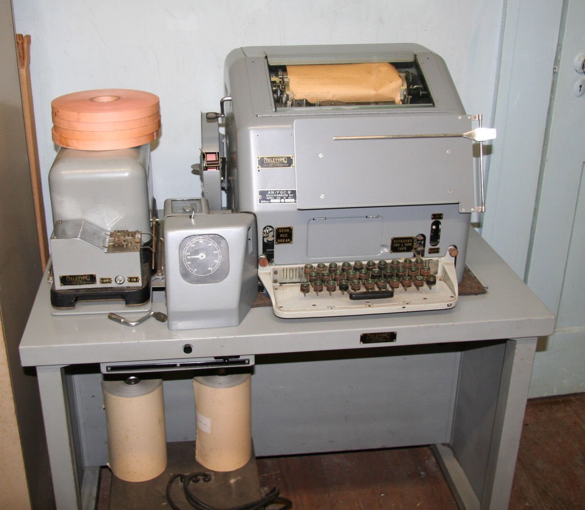
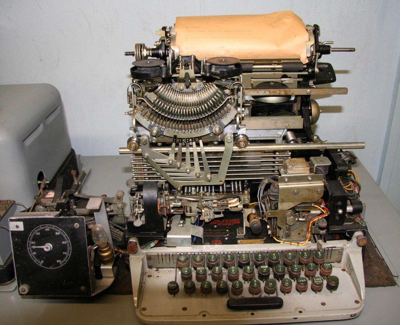
7.7 The torn-tape relay
The tape machines made possible the torn-tape relay, the way large networks moved traffic from the 1930s to the 1960s. A message arrived at a relay centre on a typing reperforator; an operator tore off the tape at the end of the message, read the routing from the characters typed on it, and carried it to the transmitter-distributor for the next circuit, where it was sent on at full speed. No message was retyped, so none was garbled by a tired operator, and a centre could switch hundreds of circuits with a room of TDs and reperforators. Paper Tape & the Perforator, Vol 2, describes the operating side.
Two details from Teletype’s documents show how the Model 15 fitted into this. The Model 15’s keyboard lockout mechanism has a second pair of contacts “used when it is desired to control a tape transmitting distributor” (P70.013), so a printer could stop a TD automatically. And Teletype’s keytop sheets show two communications arrangements for Model 14 keyboard perforators, JU and KH, with the FIGS-H position left blank, because “it is not intended that the figures ‘H’ motor stop mechanisms will respond correctly when the figures ‘H’ combination is transmitted automatically from tape” (1948 list, keytop sheets). A motor-stop code punched into a relay tape would have switched off every printer downstream.
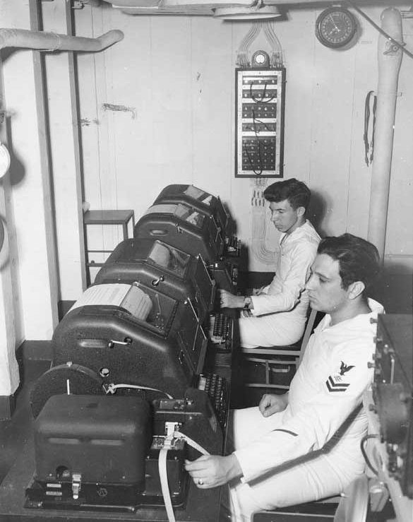
7.8 Tape with a computer today
Tape equipment connects to a computer in exactly the same way as the Model 15 itself, because a TD and a reperforator are both just devices on a 60 mA loop (Volume 6).
- Reading tape into a computer. Put the TD on a loop with a receive interface. Each character the TD reads arrives at the computer as a 45.45-baud start-stop character, the same as a key pressed on the keyboard. A box of old tapes can be read this way and saved as files.
- Punching tape from a computer. Put a reperforator’s selector on a loop driven by a send interface, and the computer can punch a tape. A typing reperforator also prints the text along the tape. A Model 15 with a perforator-transmitter keyboard can punch tape locally while the computer listens to the keyboard loop.
- Half duplex makes it simple. CuriousMarc wired his Model 19 table half duplex, with “the printer, keyboard, TD and reperforator” all in one loop, so whatever any of them sends, all of them receive and the reperforator records (CuriousMarc).
- Brag tapes and RY tapes. Amateur RTTY operators kept tapes of station descriptions, test patterns (RYRYRY, the quick brown fox) and art (pictures typed in characters, of the kind RTTY.COM collects in its gallery) to send from the TD. A tape of RY is the standard test signal for taking a range (Volume 5).
- Modern readers. Optical tape readers and microcontroller-driven punches can stand in for a TD or reperforator, but a Model 14 TD reading a tape at a steady 368 characters a minute is the period method, and the one that makes a Model 15 installation complete.
7.9 Should a Model 15 owner bother?
For the PURPLE replica (Volume 8), no tape equipment is needed: the machines only type and print. For a complete period station, a TD and a reperforator add a great deal. Messages can be prepared offline and sent at a steady speed, and received traffic can be kept on tape. They also add weight, another motor, another set of adjustments and another loop supply for the perforator magnets.
The practical advice is to start with the Model 15, get it running cleanly on a local loop and an interface, and add tape equipment once the printer works. Much of the documentation (S-5321, the lubrication rules, the TD and reperforator bulletins) is already staged in the Library with this dive.
7.9.1 Sources (Vol 7)
- Model 14 history and numbers; Model 14 tape punch 1941; Models 19 and 20 1946–50 — Don Robert House, A Synopsis of Teletype Corporation History (2001). http://simson.net/ref/2001/house-teletype-corp-synopsis.pdf
- Model 14 typing reperforator (definition, chadless 11/16-inch tape, letters and figures positions, message-centre use, options) — Teletype Corporation, Bulletin 172B, Typing Reperforator (Model 14), issue 2 (October 1943). ⟨staged for the Library⟩
- Transmitter-distributor (definition, five- and six-unit and two-channel versions, tape pins and contact tongues, brushes and segments, 23 cps at 368 opm, tight-tape and end-of-tape stops, lubrication) — Teletype Corporation, Bulletin 141B, change 2 (1964). ⟨staged⟩
- Army designations and tuning forks for Model 14 TDs — War Department TM 11-2222 (1951). ⟨staged⟩
- Set lists; Model 19 composition, weight and dimensions (sheet 4.D1-1); 100-wpm TD (sheet 19D5, 1954); JU and KH keytop arrangements — Teletype Corporation, Teletype Equipment List, issue 2 (1948, sheets 1943–1954). ⟨staged⟩
- The Model 19 documentation set — Teletype Corporation, 5MA, Model 19 Set (September 1942). ⟨staged⟩
- Motor and gear interchange for Model 14 reperforators and TDs — Teletype specification S-5321 (1941). ⟨staged⟩
- TT-7/FG, TT-8/FG, TT-53/FG, TT-74/FG, TT-52/FG — JANAP 161, Change 1 (1956), Part 2. https://navy-radio.com/manuals/janap161-5610-Part2.pdf
- Perforator keyboard on a Model 15 and its 500 mA, 110 V DC supply — RTTY Inc. Model 15 notes, RTTY.COM. https://rtty.com/development/teletype/model-15/index.html
- Keyboard lockout contacts for TD control — BSP P70.013 (1951), p. 19.
- A Model 19 table wired half duplex — CuriousMarc. https://www.curiousmarc.com/computing/teletype-model-19
- Cross-links: Interfacing Teletypes and Paper Tape (tape readers and punches on a computer); Paper Tape & the Perforator (the tape, reading it by hand, chad, torn-tape relay); Volumes 4–6 and 8 of this dive.