The Teletype Model 15 · Volume 6
The Teletype Model 15 — Vol 6: The Loop and the Computer
The 60 mA neutral loop from first principles, why it runs at over a hundred volts, how to build or buy a supply that will not hurt anyone, and how to connect the machine to a PC, a Raspberry Pi, a microcontroller or a radio.
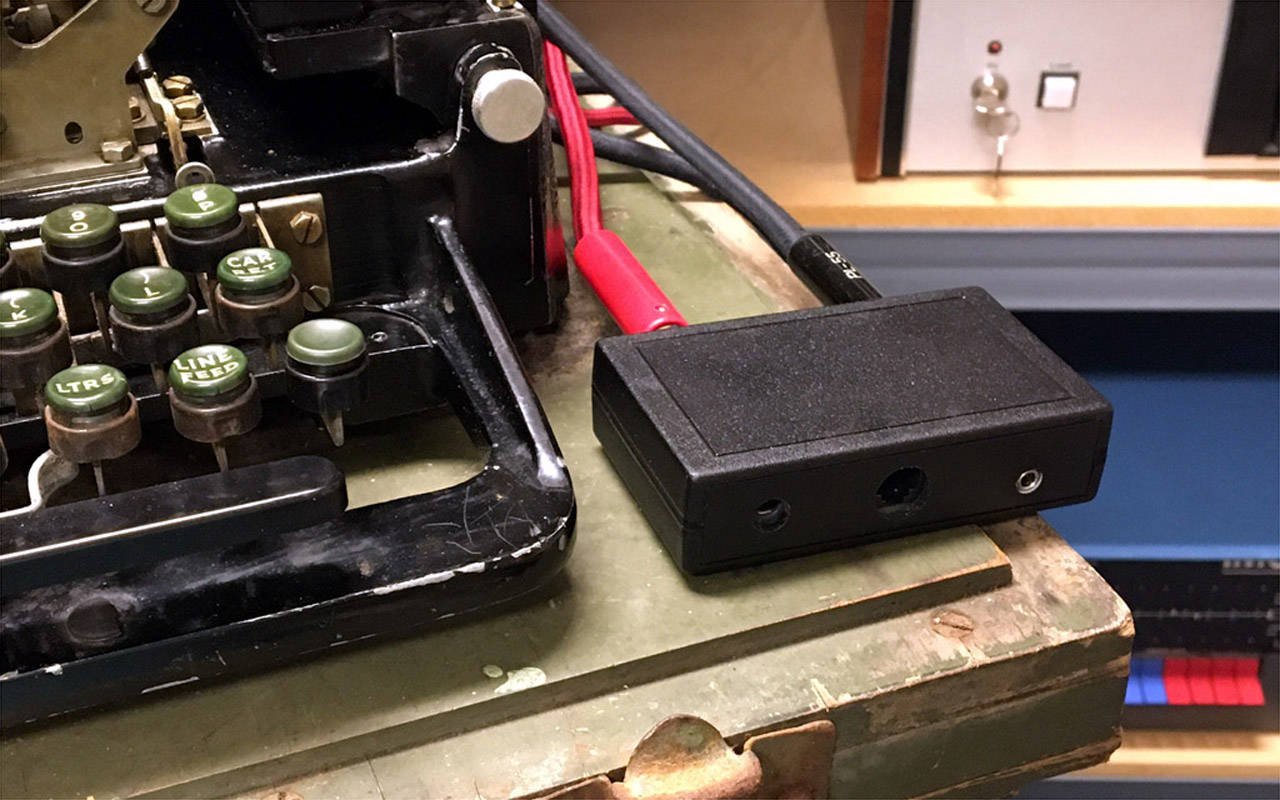
6.1 Where this volume starts
Restoring a Teletype gives the short version: you cannot plug a teleprinter into a computer, because it is a current loop and not a voltage interface, it speaks Baudot and not ASCII, and it runs at 45.45 baud, a speed most serial adapters will not reach. Making the Parts That No Longer Exist describes the best modern answer, the DeRamp regenerative loop interface. The sibling dive Interfacing Teletypes and Paper Tape covers loop interfaces, ITTY reception and tape equipment for every Teletype model in step-by-step detail; this volume is the Model 15’s own account. It goes through the whole electrical side of the machine in order: the loop itself, the numbers that set its voltage, supplies old and new, the wiring choices inside the machine, the interfaces that exist, the software that drives them, and how to put the result on the air.
6.2 The loop, from first principles
A Model 15 signals by switching a direct current on and off in a series circuit. Everything that sends or receives is in that circuit:
- the loop supply, a source of DC;
- a current-setting resistance;
- the selector magnet of every printer on the loop, which pulls its armature in when current flows;
- the keyboard transmitting contacts of every keyboard on the loop, which open and close the circuit as a character is sent.
Current flowing is mark; no current is space. The line idles marking, so a healthy idle loop carries its full current continuously and the selector armature sits pulled up, holding the receiving mechanism latched (Inside the Teletype Mechanism, Vol 1). A broken wire looks like a permanent space, which the selector reads as an endless string of start elements, and the machine “runs open,” cycling and printing nothing. That is the first symptom of a loop fault, and the reason a Model 15 with nothing connected to it clatters.
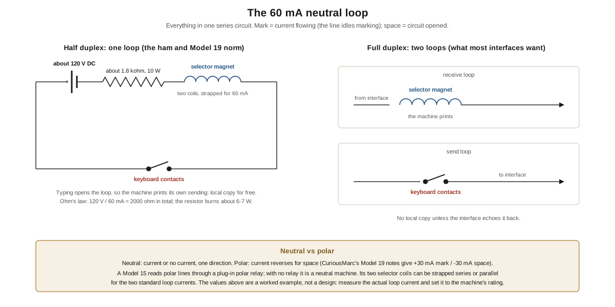
Neutral versus polar. In a neutral loop the current is on or off, in one direction. In a polar loop it reverses: one direction for mark and the other for space (CuriousMarc’s notes on his Model 19 give +30 mA and −30 mA). Polar working was used on long lines and some military circuits because the receiving relay is driven positively in both states rather than relying on a spring to release it. A Model 15 copies polar signals through a plug-in polar line relay on the base, when one is fitted; a machine with no relay is a neutral machine. Volume 3 covers how to tell which a machine has. For amateur and computer use, neutral is almost always what is wanted, and the RTTY Inc. notes for hams give the wiring for both cases (rtty.com).
60 mA or 20 mA. The Model 15’s selector magnet has two coils that can be strapped in parallel for a 60 mA line or in series for the lower-current lines. A collector’s Model 15 arrived with its selector switch set to “Parallel (60 mA)” (circuitousroot, Model 15 KSR base 213102), and Teletype’s adjustment bulletin specifies the magnet’s pull test “when a current of .020 ampere is flowing through the magnet coils (coils in series shunted by 5000 ohm resistance)” (Teletype Bulletin 138B, Adjustments of Model 15 Printer, 1944). The standard for amateur and hobby use is 60 mA, coils in parallel. Volume 5 explains why the selector armature spring tension depends on which strapping is used.
6.3 Why the voltage is so high
The loop supply on a classic installation is around 120 V DC. The data plate on the circuitousroot machine reads “120 Vdc, 60 mA” for the line. A first-time builder often asks why, when the magnet only needs 60 mA and its coils have a resistance of only about a hundred ohms (the TG-7 parts index in TM 11-352 lists a 105-ohm magnet coil on its selector-magnet figure). The answer is inductance.
The selector magnet is a big electromagnet with an iron core. Trammell Hudson’s notes on his Model 15 quote John Nagle’s estimate of about 4 henries (trmm.net). Current in an inductor cannot change instantly; it rises toward its final value with a time constant
tau = L / R_totalwhere R_total is the whole loop resistance. The element the magnet has to follow is 22 ms long at 60 words per minute, and the selector samples it in the middle (Volume 2). For a clean signal the current must reach most of its final value within a small part of that element:
low-voltage loop:   12 V / 60 mA = 200 ohm total    ->  tau = 4 H / 200 ohm  = 20 ms
classic loop:      120 V / 60 mA = 2000 ohm total   ->  tau = 4 H / 2000 ohm =  2 ms
A 12-volt loop would take about one whole element to rise, so every mark would arrive late and soft. A 120-volt loop with a large series resistor reaches 63 per cent of full current in 2 ms and 95 per cent in 6 ms, well inside the element. The high voltage is not there to push 60 mA through the coil. It is there so that a large series resistance can be used, which makes the circuit’s time constant short. The same reasoning explains the old operator’s rule that you do not “fix” a weak loop by lowering the resistance and the voltage together.
The cost is heat. With 120 V and 60 mA, about 7.2 W goes into the loop, and nearly all of it is dissipated in the series resistor:
P = I^2 x R = (0.060 A)^2 x 1800 ohm = 6.5 WTrammell Hudson puts the waste at “6 W”; it is the same figure. A resistor for that duty should be rated several times higher, 25 W or so, and mounted where its heat can go somewhere. Making the Parts That No Longer Exist describes how the DeRamp interface removes the waste altogether by recovering the coil’s own stored energy.
Release matters as much as pull-in. When the loop opens for a space, the magnet’s stored energy has to go somewhere. Left alone it produces a voltage spike across the opening contacts or transistor (hundreds of volts, briefly) that arcs keyboard contacts and kills semiconductors. The obvious fix, a plain diode across the coil, is the wrong one: it lets the current circulate through the coil’s own small resistance, so the field collapses with a time constant of L divided by the coil resistance, far longer than a 22 ms element. The armature then releases late and the range narrows. The right fixes clamp the spike at a high voltage, so that the energy is absorbed quickly: a zener or TVS diode rated well above the loop voltage across the switch, a resistor-capacitor snubber, or the DeRamp board’s regenerative capture, which stores the 40–60 V spike and returns it on the next mark (DeRamp).
6.4 Loop supplies: classic, adapted, and modern
The original. A military TT-5/FG set came with a REC 29 rectifier power unit, 46 lb on its own (JANAP 161); a Model 19 had the bigger REC 30. CuriousMarc’s Model 19 supply is a high-voltage unit using thyratron tubes, rebuilt from a schematic glued inside its door (CuriousMarc). An original rectifier is worth keeping for display. It needs a complete recapping and a careful check before it is trusted with a loop.
The hobbyist classic. For decades the standard home-built loop supply has been a transformer, a bridge rectifier, a filter capacitor and a big wirewound resistor, with an adjustable resistance and a milliammeter so the current can be set. The usual ham practice is to use an isolation transformer, so that nothing in the loop is referenced to the mains neutral, with a fuse in the primary and a fuse in the loop.
The modern regenerative board. The DeRamp Model 15 interface needs no high-voltage supply at all. It runs from a 15 V AC adapter, generates the 60 mA loop itself, and uses its regenerative snubber to get the fast pull-in and release that the 120 V supply provided. It is offered as a bare board with a pre-programmed PIC for $20 plus shipping, the buyer supplying the parts (DeRamp).
Boost converters. Trammell Hudson’s interface for his Model 15 generates its high voltage with a PWM charge pump and a boost inductor from USB power and switches the loop with a second MOSFET, appearing to the host as an ordinary USB serial port (trmm.net). John Nagle’s TTYLoopDriver takes the same approach, deriving its loop voltage from USB power; CuriousMarc notes that its drivers are hard to find (CuriousMarc).
Safety. A 120 V DC loop is dangerous. DC does not pass through zero 120 times a second the way mains does, so a hand that closes on it can be held. Every loop supply in this volume should be isolated from the mains and from any computer it is connected to, fused, enclosed so that no live terminal can be touched, and switched off before anyone works on the machine. The Model 15’s terminal blocks are bare screws, and the line runs to them. Put a cover over them.
6.5 Wiring inside the machine
A Model 15’s base has terminal blocks that bring the selector magnet, the keyboard contacts, the motor and any relay out to numbered screws. The RTTY Inc. notes for hams give the simplest case: with no polar relay, the loop goes to terminals 41 and 42; with a polar relay fitted, leads are moved between terminals 61, 62, 65 and 66 and the relay lead on 61 is taped off. The keyboard plugs into the base and connects to terminals 32 and 34 (rtty.com). Terminal numbering varied with the installation and the base, so the wiring diagram for the actual machine (Volume 3: find the base code) is the authority. Making the Parts That No Longer Exist and the restoration accounts both warn that previous owners often rewired machines, so a diagram from the right model may still not match what is in the base.
Half or full duplex. For half duplex, the keyboard contacts and the selector magnet go in series on one loop: the machine prints whatever is typed on it, and whatever arrives on the line. For full duplex they come out on separate pairs. The DeRamp board requires full duplex, “separate transmit and receive loops,” and can supply the local copy itself by echoing (DeRamp). CuriousMarc rewired his Model 19 table for half-duplex neutral, with the printer, keyboard, TD and reperforator in one loop, a local test loop, and two line jacks that assume the far end supplies the power.
Connectors. Quarter-inch phone plugs on short cords are the traditional way to bring loops out of a Teletype installation, and the DeRamp board uses two of them, one for send and one for receive.
6.6 Interfaces you can buy or build
Table 1 — Interfaces you can buy or build
| Interface | What it does | Host side | Loop side | Source |
|---|---|---|---|---|
| DeRamp Model 15 interface | ASCII↔Baudot, speed conversion, AFSK demodulator, regenerative loop drive; escape sequences for characters the keyboard lacks | RS-232, 9600 8N1, with flow control | 60 mA neutral, full duplex; 60, 67, 75 or 100 wpm; US-TTY or ITA2 | deramp.com |
| Volpe board / epvuc usb-tty | USB CDC serial on an ATmega32U2/32U4; translating or transparent mode; unshift on space; ASCII mode for Model 33s | USB | Needs an external loop supply; 45.45, 50, 56.9 or 74.2 baud | teletype.net, GitHub |
| TTYLoopDriver (John Nagle) | USB adapter that makes its own loop voltage | USB serial | 60 mA | via CuriousMarc |
| trmm.net boost interface | PWM charge pump, MOSFET loop switch, ASCII↔Baudot with shift tracking | USB serial | 60 mA from USB power | trmm.net |
| CuriousMarc’s box | Arduino Mega with an analog board based on Eric Volpe’s design | USB | external supply | curiousmarc.com |
| Vintage terminal unit | ST-5/ST-6, HAL and similar: demodulate audio and key a loop | audio from a receiver | its own loop supply (high voltage) | RTTY on the Air |
The epvuc firmware’s README gives the timer values for the four standard speeds, which double as a reminder of what those speeds are: 45.45 baud (60 wpm), 50.00 (66), 56.90 (75) and 74.20 (100) (epvuc/usb-tty).
6.7 Building your own
Every interface in the table follows the same pattern, and a builder with a microcontroller can follow it too.
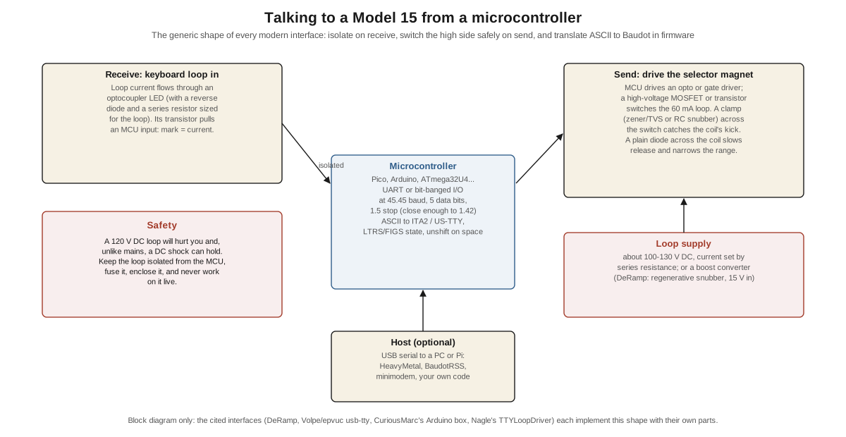
Receive (keyboard to computer). Put an optocoupler’s LED in series with the keyboard loop, with a reverse-protection diode across it and, if needed, a shunt resistor so that the 60 mA loop current does not exceed the LED’s rating. The isolated phototransistor pulls a microcontroller input low on mark. Nothing on the computer side is then connected to the loop.
Send (computer to printer). Put a switching element rated well above the loop voltage, a MOSFET or high-voltage transistor, in series with the selector magnet, and drive it through an optocoupler or isolated gate driver. Across the switch, fit a clamp that limits the turn-off spike to a safe voltage above the supply (a TVS or zener rated for the energy, or an RC snubber), and not a plain diode across the coil, for the reasons above.
Timing. At 45.45 baud each element is 22 ms. A microcontroller sends a start element (space), five data elements with element 1 first, and a stop element of mark for 1.42 units (31 ms), or 1.5 units, which the machine tolerates. The receive side waits for a mark-to-space edge, waits half an element, checks that the line is still spacing, then samples the five elements at their centres, the same rule the Model 15’s selector follows mechanically. Lorenz and Colossus Volume 13 on the Iconic Machines site describes exactly this receiver as a pair of Raspberry Pi Pico PIO programs; a PIO state machine (or a timer interrupt) is the right tool because the RP2040’s hardware UARTs cannot be divided down below about 119 baud (Volume 8).
Translation. The firmware keeps the machine’s shift state. To print a figure it sends FIGS first if the machine is in letters, and LTRS before the next letter. Characters that ITA2 and US-TTY lack (lower case, @, %, *, +, = in US-TTY) are dropped or spelled out; the DeRamp board offers escape sequences for them. Unshift on space is wise in both directions: the Model 15 has a lever for it (Volume 2), and a translator that sends LTRS after every space recovers quickly when a noise burst leaves the machine in figures.
6.8 Software
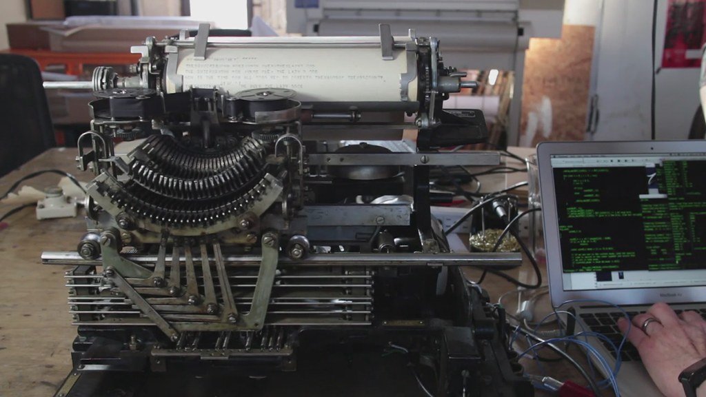
- HeavyMetal, a graphical program for driving a teleprinter from Windows or Linux, often described as a PuTTY for teletypes: it manages the serial port settings (baud, data and stop bits, ITA2 or US-TTY) and provides a glass-TTY window (Retrocomputing Forum). It does its own Baudot conversion, so it pairs with interfaces run in transparent mode.
- BaudotRSS (John Nagle) prints news feeds and National Weather Service forecasts on a Baudot machine, with
--ryrypatand--alphapattest patterns; it supports USTTY, ITA2 and a fractions character set and recommends full duplex because “half duplex can produce garble.” Its documentation notes that a classic PC serial port can be set to 45 baud directly, while a USB converter has to be reprogrammed so that a requested 600 baud produces 45 (Aetheric). - A Linux login. CuriousMarc runs a Linux shell on his Model 15/19 through his interface, with the host side at 9600 baud and XON/XOFF flow control, and notes the limits: 74 columns and capitals only (CuriousMarc). Hackaday’s “Logging Into Linux With A 1930s Teletype” covers the same build.
- minimodem generates and decodes audio frequency-shift keying in software; its
rttymode is 45.45 bit/s Baudot with 1.5 stop bits, andminimodem --rx -a rttydecodes amateur RTTY from a receiver (minimodem(1)). - fldigi and MMTTY decode RTTY in a sound card (Modern Digital and the Raspberry Pi); their text output can be fed to a Model 15 through a translating interface.
6.9 RTTY on the air with a Model 15
This is the job most surviving Model 15s did after the war, and it is still the most satisfying thing to do with one. There are three ways to do it.
The classic chain. Receiver audio goes into a terminal unit (an ST-6, a HAL, a Flesher), which filters the mark and space tones, decides which is present, and keys a loop. The Model 15 prints. For transmit, the keyboard’s loop keys the terminal unit’s FSK or AFSK output into the transmitter. RTTY on the Air describes the terminal units and the tuning scope. The HAL ST-6 manual (1974), staged for the Library with this dive, shows what a terminal unit of the classic kind provides: an internal 175 V, 60 mA series loop supply for the printer’s selector magnet and keyboard, a data filter of 27 Hz for 60 wpm (45 baud) or 45 Hz for 100 wpm (75 baud), and an autostart that turns the printer motor and loop off after about 30 seconds without a signal and back on when one appears.
The sound-card chain. fldigi or MMTTY decodes the signal on a computer, and the text goes to the Model 15 through a translating interface. This is the easiest way to get good copy on a weak signal, because software demodulators are better than most vintage terminal units, but the machine only prints and does not decode.
The DeRamp chain. The DeRamp board has an AFSK input: line-level audio at 2125 Hz mark and 2295 Hz space, on a 3.5 mm plug, which it demodulates itself (DeRamp). Fed from a receiver’s audio output, it is a complete modern terminal unit and loop supply in one, with the Model 15 as the printer.
Operating settings. Amateur RTTY is 45.45 baud, 170 Hz shift, with the tones conventionally 2125 Hz mark and 2295 Hz space and the transmitter on LSB; RTTY on the Air explains the sideband convention. Set the Model 15’s unshift-on-space lever on: when static turns a few characters into a FIGS code, the machine returns to letters at the next space instead of printing a line of numbers. Take a range on the local loop first (Volume 5). If the range is good locally and narrow off the air, the fault is the signal, not the machine.
6.10 Printing the news again: ITTY
A Model 15 was built to sit in a newsroom printing the wire, and it can still do that. ITTY, run by the RTTY.COM archive (Volume 5), broadcasts live Baudot RTTY as internet audio, 24 hours a day, from Arvada, Colorado, for real machines to print (RTTY.COM, “ITTY”):
Table 2 — A Model 15 was built to sit in a newsroom printing the wire, and it can still do that. ITTY, run by the RTTY.COM archive (Volume 5), broadcasts live Baudot RTTY as internet audio, 24 hours a day, from Arvada, Colorado, for real machines to print ([RTTY.COM, "ITTY"](https://rtty.internet-tty.net/itty.html))
| Channel | Speed | Tones | What it carries |
|---|---|---|---|
| ITTY | 60 wpm, 45.45 baud | 2125 / 2295 Hz | wire-service news articles, loaded daily |
| AUTOSTART | 60 wpm, 45.45 baud | 2125 / 2295 Hz | a daily “This Day in History” bulletin, articles sent in by users, and selected GreenKeys messages |
| ITTY 100 | 100 wpm, 75 baud | 2125 / 2295 Hz | the same news, faster |
| ITTY Europe | 66 wpm, 50 baud | 1275 / 1445 Hz | European news from RSS feeds |
All channels use 170 Hz shift. The 60 wpm channels are exactly the Model 15’s speed. The stream for the main channel is internet-tty.net:8000/ITTY; the others are listed on the ITTY page.
Printing it takes the same chain as radio RTTY with a different audio source: stream audio → terminal unit → loop → Model 15. Any of the three chains above will do: a vintage terminal unit (an ST-6 with autostart will turn the machine on when copy begins), software decoding into a translating interface, or the DeRamp board’s AFSK input fed straight from a computer’s headphone socket. ITTY’s own instructions say exactly that: route the audio to an FSK demodulator set for 170 Hz shift at the channel’s speed and connect its loop output to the machine.
ITTY is also the best test signal a restorer has. It is clean, continuous and at the right speed, so a range taken on ITTY (Volume 5) measures the machine, not the band conditions. And it lets a restored Model 15 do the job it did for thirty years, printing the day’s news unattended.
6.11 What a good interface checklist looks like
Before connecting a Model 15 to anything:
- Measure the loop current with a meter in series. Set it to 60 mA (or the machine’s strapping).
- Check that nothing on the computer side has continuity to the loop or to the machine’s frame.
- Confirm the selector coils’ strapping (parallel for 60 mA) and that any polar relay is out or wired correctly.
- Decide half or full duplex, and wire the base to match (Volume 3 for the diagram).
- Run the machine on a local test loop and take a range before connecting the interface. Then take it again through the interface. The two numbers should agree.
6.11.1 Sources (Vol 6)
- Selector magnet inductance (~4 H, after John Nagle); the 100 V supply wasting ~6 W; the USB boost-converter interface — Trammell Hudson, “Model 15 Teletype.” https://trmm.net/Model_15_Teletype/
- Selector magnet pull test at .020 A with coils in series shunted by 5000 ohm; armature spring tensions by coil strapping — Teletype Corporation, Bulletin 138B, Adjustments of Model 15 Printer, issue 5 (1944), pp. 22–26. ⟨staged for the Library⟩
- Selector switch found at “Parallel (60 mA)”; line plate 120 Vdc, 60 mA; module serials — circuitousroot, “Teletype Model 15 KSR, Base 213102.” https://www.circuitousroot.com/artifice/telegraphy/tty-stuff/cr-tty/tty-15-ksr-213102/intro/index.html
- Terminals 41/42, 61/62/65/66 and 32/34; series/parallel coils; unshift on space — RTTY Inc. Model 15 notes, rtty.com. https://rtty.com/development/teletype/model-15/index.html
- DeRamp Model 15 interface (15 VAC; regenerative snubber capturing 40–60 V; PIC16F1824; RS-232 9600 8N1; AFSK 2125/2295 Hz; 60/67/75/100 wpm; US-TTY or ITA2; full duplex; $20 board + PIC) — Mike Douglas, deramp.com. https://deramp.com/model15_interface.html and the User Manual (Oct 2025). https://deramp.com/downloads/teletype/Model%2015/loop%20interface%20board/User%20Manual.pdf
- usb-tty firmware (ATmega32U2/32U4, LUFA CDC, translating/transparent, unshift on space, baud table) — epvuc, GitHub (2016). https://github.com/epvuc/usb-tty; Volpe USB interface board — teletype.net. https://teletype.net/exportword?pageId=327728
- CuriousMarc’s Model 14/15/19 restoration (polar ±30 mA, thyratron supply, half-duplex table wiring, TTYLoopDriver, Volpe board, Arduino interface, BaudotRSS, Linux login at 9600 with XON/XOFF). https://www.curiousmarc.com/computing/teletype-model-19
- BaudotRSS — John Nagle, Aetheric. https://www.aetherltd.animats.com/communicating.html
- HeavyMetal — Retrocomputing Forum thread. https://retrocomputingforum.com/t/using-a-teletype-on-modern-pc-heavymetal-tty-control-program/3880
- ITTY (channels, speeds, tones, stream addresses, connection method) — RTTY.COM, “ITTY.” https://rtty.internet-tty.net/itty.html (read 3 November 2026)
- HAL ST-6 manual (175 V 60 mA loop, data filters, autostart) — Hal Communications, ST-6 RTTY Demodulator (1974). ⟨staged for the Library⟩
- minimodem rtty mode — minimodem(1) manual page. https://manpages.opensuse.org/Tumbleweed/minimodem/minimodem.1.en.html
- REC 29 / REC 30 rectifiers — JANAP 161, Change 1 (1956), Part 2. https://navy-radio.com/manuals/janap161-5610-Part2.pdf
- Time-constant and dissipation figures are computed in the text from the cited inductance and loop values.
- ⚠ Safety: loop supplies of about 120 V DC and mains-powered motors are dangerous. This volume describes practice; it is not a substitute for competence with high-voltage work.
- Cross-links: Interfacing Teletypes and Paper Tape (the full how-to, all models); Teletype Model 28 (the successor); Restoring a Teletype (why you cannot just plug it in); Making the Parts That No Longer Exist (the DeRamp interface in depth); RTTY on the Air; Modern Digital and the Raspberry Pi.