The Teletype Model 15 · Volume 2
The Teletype Model 15 — Vol 2: How It Works, Unit by Unit
Four boxes that bolt together: a typing unit, a keyboard, a base and a motor. The code they speak, the gear train that keeps them in time, and every function the machine performs, from the selector to the carriage-return dashpot.
2.1 A machine made of modules
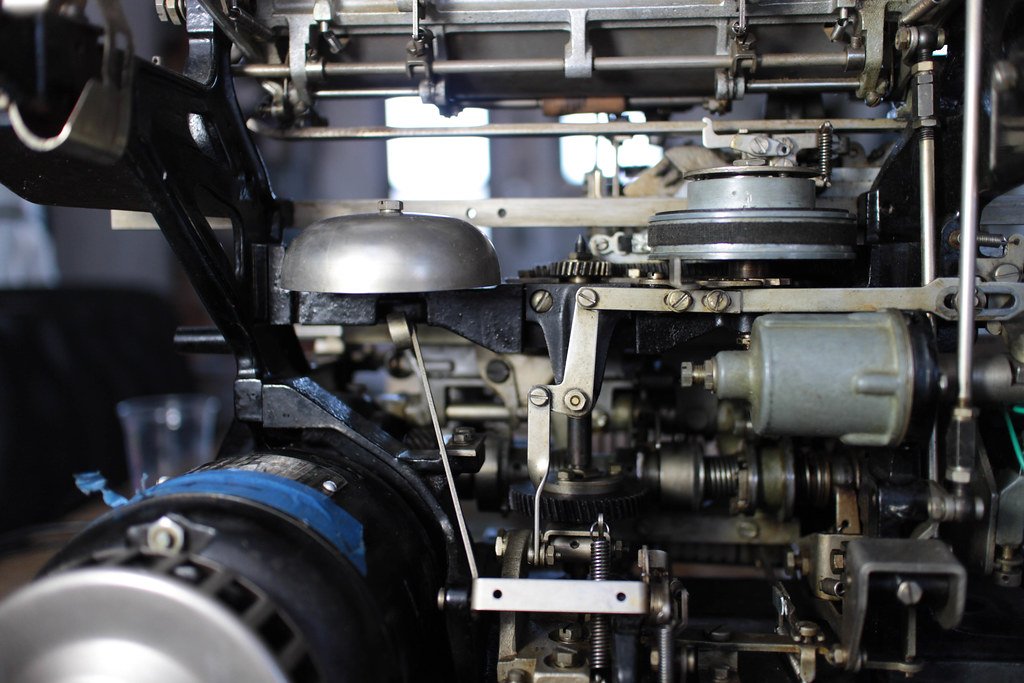
Inside the Teletype Mechanism follows a single character through a Model 15: the selector, the swords, the code bars, the pull bar, the type bar. This volume takes the other approach. It goes through the machine unit by unit, the way Teletype built it, sold it and documented it, and the way a restorer takes it apart. Where the earlier dive already explains a mechanism in detail, this one gives the numbers and cross-links to it.
Teletype’s 1946 general description of the Model 15 sending-receiving page printer set lists what a customer received, each item with its Teletype code prefix (Teletype Equipment List, issue 2, 1948, sheet 2.D1-1):
Table 1 — Teletype's 1946 general description of the Model 15 sending-receiving page printer set lists what a customer received, each item with its Teletype code prefix (Teletype Equipment List, issue 2, 1948, sheet 2.D1-1)
| Code | Unit | Notes |
|---|---|---|
| BP | Typing unit | friction or sprocket paper feed; type arrangement as specified |
| BB | Base | terminal blocks, mounting, wiring |
| MU | Motor unit | synchronous or governed |
| Set of gears | different ratios for synchronous and governed motors | |
| BK | Keyboard | keytop arrangement as specified |
| RY | Line relay | optional, for polar or long lines |
| C | Cover | with a front plate for sending-receiving or receive-only |
| XRT | Table | |
| REC | Rectifier | for the loop supply; not needed at DC stations |
| Speed indicator | ”required with governed motors” |
The complete set on its table weighed 166 lb net (228 lb packed), stood 18 by 21½ inches and 42 inches high, and drew about 160 W at 115 V including its rectifier; the table alone was 45 lb. Each unit carried its own serial number, which is why a collector’s machine can have a base, motor, typing unit and keyboard from different years (Volume 3).
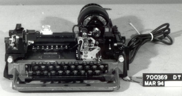
Bell System Practices section P70.013 gives the same breakdown in one sentence: “A sending-receiving machine consists of a keyboard transmitting unit, base, typing unit, and cover” (BSP P70.013, p. 2). The motor bolts to the base and drives the typing unit through a pinion and gear; the keyboard plugs into the base and is driven from the typing unit’s main shaft; electrical connections between the units are made through spring slip connections on the base, so each unit can be lifted out without unsoldering anything.
2.2 The code, and the arithmetic of 60 words per minute
The Model 15 speaks the start-stop five-unit code. P70.013 describes it: “five selecting impulses used in various combinations of current and no-current intervals. Each group of five selecting impulses is preceded by a start impulse and followed by a stop impulse.” Impulses that operate the selector magnet are marking; those that do not are spacing. Teletype Machines covers the code table and the LTRS/FIGS shift.
The timing is the part that matters for an interface (Volume 6). On a 60-speed line:
- Each unit (the start element and each of the five code elements) lasts 22.0 ms, which is 45.45 baud.
- The stop element lasts 1.42 units, 31.2 ms.
- A whole character is 7.42 units, 163.2 ms.
- That is 367.6 characters per minute, which Teletype and the military rounded to 368.1 operations per minute (JANAP 161, TT-5/FG).
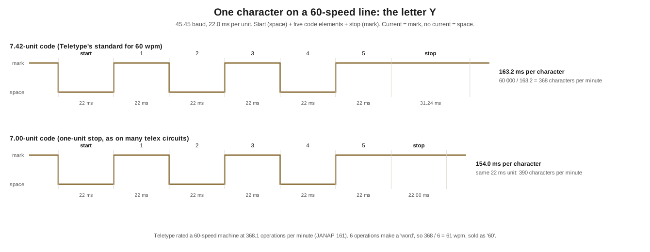
Why “60 words per minute”? A telegraph “word” was counted as five letters and a space, six operations. 368 ÷ 6 is 61.3, which the trade called 60. The other standard speeds follow the same pattern:
Table 2 — Why "60 words per minute"? A telegraph "word" was counted as five letters and a space, six operations. 368 ÷ 6 is 61.3, which the trade called 60. The other standard speeds follow the same pattern
| Speed name | Operations per minute | Baud (7.42-unit) | Unit length | Where it was used |
|---|---|---|---|---|
| 60 wpm | 368.1 | 45.45 | 22.0 ms | Bell System, US military, amateur RTTY |
| 66 wpm | 404 | 50.0 | 20.0 ms | US military option (TG-7-A, TT-5/FG); the European/telex rate |
| 75 wpm | 460 | 56.9 | 17.6 ms | commercial and press circuits |
| 100 wpm | 600 | 74.2 | 13.5 ms | later commercial circuits; amateur from 1972 |
Operations per minute for 60 and 66 wpm from JANAP 161; baud values from the epvuc usb-tty firmware’s speed table (GitHub); 75 and 100 wpm conversions are the subject of Teletype specification 5482S (1958), “modifying a Model 15 printer from 60 W.P.M. operation to either 75 W.P.M. … or 100 W.P.M.” (navy-radio.com index). Teletype later issued kits (50122S, 50138S) to convert equipment between 7.42-unit and 7.00-unit codes.
7.42 versus 7.00 units. Teletype’s own equipment sent a stop element of 1.42 units. Many telex and international circuits used a one-unit stop, a 7.0-unit character, and Western Union’s telex machines were commonly set to 390 operations per minute on that basis. Because the Model 15’s selector waits for each start element and runs one-seventh faster than the transmitter (next section), a 7.42-unit machine receives 7.0-unit signals at the same unit length without difficulty. A 7.0-unit machine receiving 7.42-unit signals just spends a little longer idle. The difference matters when sending from a computer: send 1.42 or 1.5 stop units to a Model 15 and it will never be pressed.
2.3 The power train and the eight-to-seven ratio
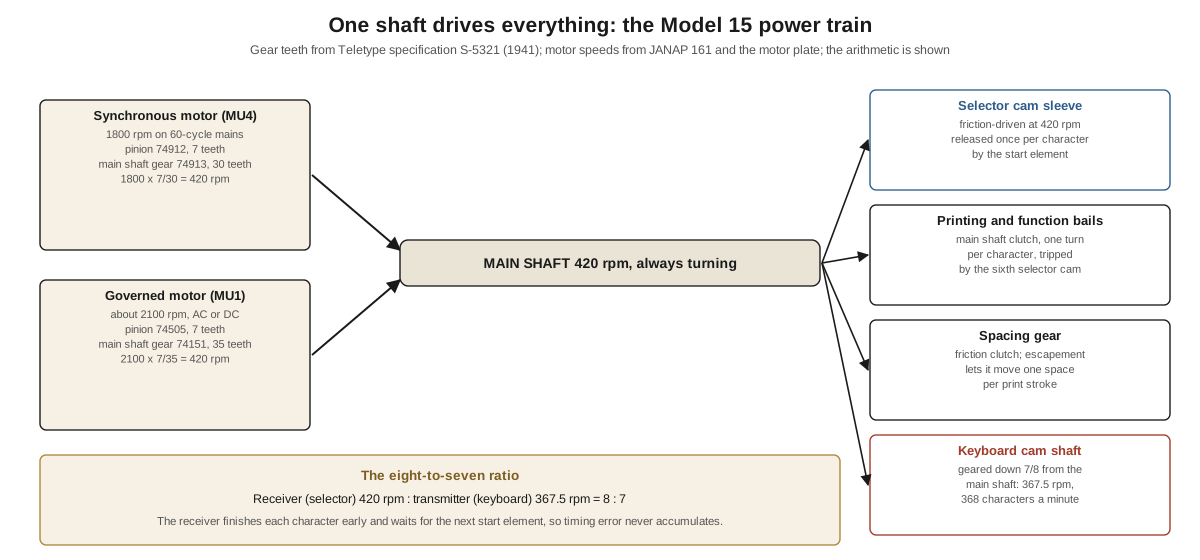
Everything in a Model 15 is driven from one continuously turning main shaft, and every action is a clutch, a cam, a bail or a spring released from it at the right moment (Inside the Teletype Mechanism, Vol 2). P70.013 lists what is on the shaft: the main shaft gear meshing with the motor pinion near the right end; the transmitting shaft driving gear that drives the keyboard; the main shaft spacing gear; the function bail cam and printing bail cam; the main shaft clutch; and, over the left end, the selector cam sleeve on its friction clutch.
Teletype’s 1941 specification S-5321, Instructions for interchanging 110 volt 60 cycle synchronous and governed motors on Teletype Model 15 printers, gives the gears for both motors:
Table 3 — Teletype's 1941 specification S-5321, Instructions for interchanging 110 volt 60 cycle synchronous and governed motors on Teletype Model 15 printers, gives the gears for both motors
| Synchronous motor | Governed motor | |
|---|---|---|
| Motor unit | MU4 (15D) | MU1 (15A) |
| Motor pinion | 74912, 7 teeth | 74505, 7 teeth |
| Main shaft drive gear | 74913, 30 teeth | 74151, 35 teeth |
| Fusetron | 103284, 3.2 A | 103286, 1.6 A |
Source: Teletype specification S-5321, issue 2, September 1941, section 1.1.
Those numbers show how the speed is set. A 60-cycle synchronous motor with a four-pole winding turns at 1,800 rpm; the circuitousroot Model 15’s General Electric motor plate reads “AC SYN … 1/40 HP, 1800 RPM” (circuitousroot). A governed series motor is held at 2,100 rpm (JANAP 161). Then:
synchronous:  1800 rpm x  7/30 = 420 rpm at the main shaft
governed:     2100 rpm x  7/35 = 420 rpm at the main shaft
Both motors give the same 420 rpm main shaft. That is the speed at which the selector cam sleeve turns once released. The keyboard cam shaft, which times the transmitted signal, turns at 368 rpm. And:
420 / 367.5 = 8 / 7This is the eight-to-seven ratio that Inside the Teletype Mechanism calls the cleverest number in the machine. P70.013 states it in words: “the selector cam sleeve is geared to rotate one-seventh faster than the transmitter cam shaft,” so that between one impulse and the next the keyboard shaft travels 48½° and the selector sleeve 55½°. The receiver always finishes its revolution early and waits for the next start element, so timing error cannot accumulate from character to character. The gear table shows where the ratio comes from: the receiving side runs at main-shaft speed and the transmitting side is geared down from it.
This is also why the speed gears are sold in pairs. Changing a Model 15 from 60 to 75 or 100 words per minute means changing the motor pinion and main-shaft gear so that the whole machine, receiver and keyboard together, runs proportionally faster. The amateur notes reproduced on rtty.com put it simply: “Normal amateur operations are at … 60 WPM, using gear wheels numbered 74912 and 74913” (rtty.com), the synchronous pair in the table above.
2.4 The motor unit: synchronous or governed
S-5321 states when each motor is the right choice: “Where the frequency of the A.C. power supply is regulated within plus or minus 3/4%, the apparatus … is generally operated by synchronous motors. When frequency variations exceed this value, governed motors should be used.”
The synchronous motor locks to the mains. On today’s grid, held far tighter than ±0.75 %, it is the trouble-free choice: no adjustment, no contacts to burn. It must, however, match the mains frequency; a 60-cycle synchronous Model 15 runs 17 per cent slow on 50-cycle power, and correcting that means a different gear pair.
The governed motor is a series (universal) motor whose speed is held by the centrifugal governor on its shaft. Inside the Teletype Mechanism describes how the governor contacts switch a resistance into the motor circuit when the speed rises and short it out when it falls. P70.013’s base illustration labels the governor brushes that carry current to the rotating contacts, and the motor adjusting screw. The governed motor will run on AC of almost any frequency and on DC, which is why the military specified it: the Army’s TG-7-A ran on 25, 50 and 60 cycles and on 115 V DC (PE1NGZ), and JANAP 161 lists its TT-5/FG as an “a-c series-governed motor; 2,100 rpm” on 25 to 60 cycles. The cost is that it has to be set: Teletype’s equipment list says a speed indicator is “required with governed motors,” and the Army set its machines with a tuning fork, 368 or 404 operations per minute “by use of proper tuning fork.” The speed indicator is the stroboscopic target and lamp described in Inside the Teletype Mechanism; the tuning fork is the field method, a vibrating fork with shutters through which the governor target is viewed. Volume 4 covers setting the speed.
Motor control. P70.013 describes two automatic ways of stopping the motor so that an idle printer is not left running all night. With mechanical motor control, the motor-stop function (below) stops every motor on the circuit when the operator sends FIGS-H, and opening the line briefly starts them again. Teletype also made separate motor control units, relay boxes that start the motor when the line opens and stop it after a period of idle mark; BSP section 572-007-100 (1964) describes those used with Models 14 and 15.
2.5 The base
The base is a cast frame that the other units sit on, and its main job is electrical. P70.013: “The base provides facilities for mounting the typing, keyboard and motor units together with the necessary accessories such as mounting blocks, condensers, slip connections, terminals, etc.” The base’s terminal blocks are where the loop, the motor supply and any accessories connect (Volume 6), and the base is the unit whose code decides which wiring diagram applies (Volume 3).
Two optional parts live on the base. A line relay can be fitted: “A line relay base is provided on 15A and 15B bases … The wiring is arranged so that either the line relay or the selector magnets may be connected in the line circuit. In the former case, the contacts of the line relay repeat the signals to the selector magnets.” A polar line relay is how a Model 15 copies polar signals. And on certain keyboards there is a Line-Test key: “When the knob of the ‘Line-Test’ key is pulled out, the selector magnets and keyboard contacts are disconnected from the line and a local circuit is established.” That is a built-in local loop for testing the machine without disturbing the line.
2.6 The keyboard
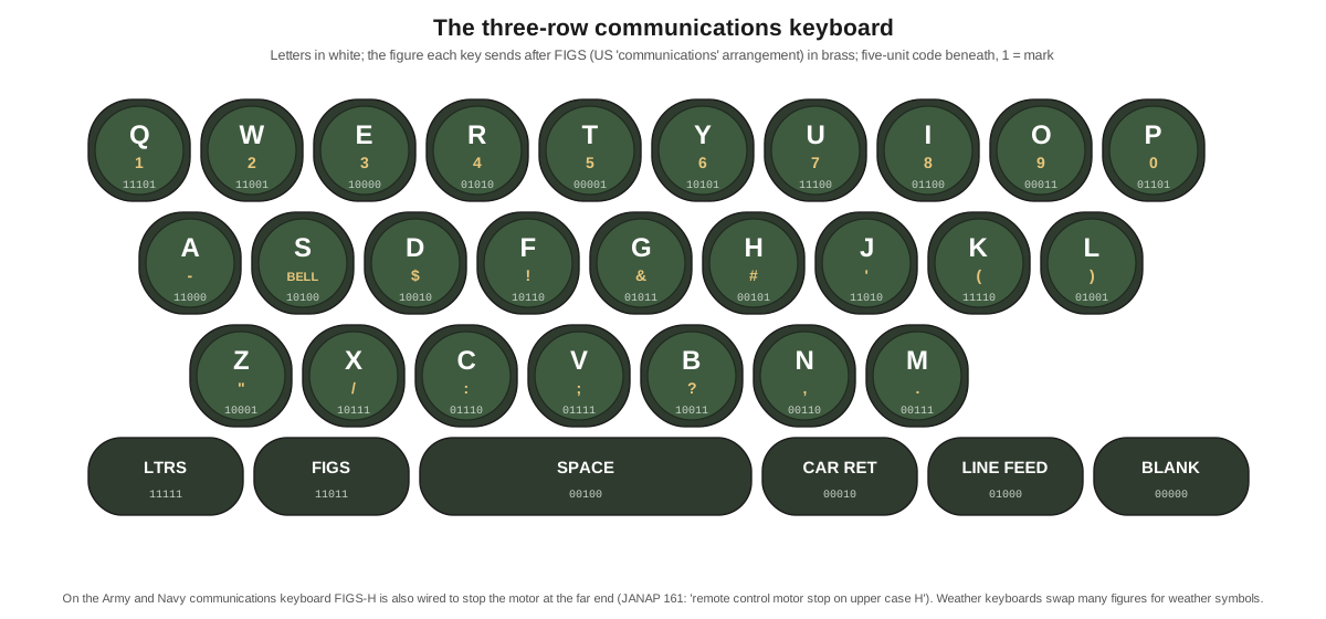
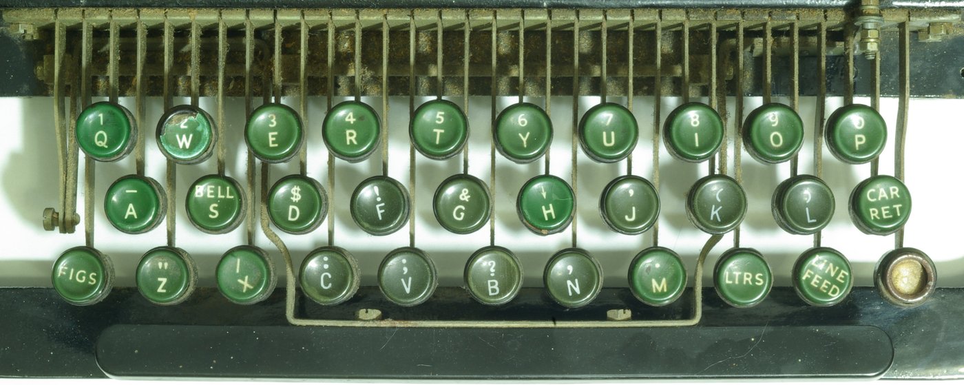
The keyboard is a mechanical parallel-to-serial converter, and P70.013 describes it step by step.
Selecting. Under the key levers lie five selector bars and a universal bar running across the keyboard. The selector bars have saw-tooth notches cut according to the code. A key lever pressed down strikes the slanting sides of the notches and slides each bar left or right, according to whether its element is to be spacing or marking. Every key also pushes down the universal bar, which works the trip-off pawl and the clutch throwout lever.
Sending. The sending cams are normally held still because the clutch members on the keyboard’s driving shaft are held apart by the throwout lever. When a key trips it, the driven member meshes and the cam sleeve makes one revolution. Each selector bar sets a vertical locking lever, and each locking lever either lets its contact lever rise into the indent of its cam and close the contact (mark) or blocks it (space). A separate start-stop cam opens the start-stop contacts at the beginning of the revolution to send the start element and closes them after the fifth element to send the stop. At the end of the revolution the clutch is cammed out of mesh and the cams stop.
Interlocking. A lock loop, raised by its cam at the end of each revolution, holds the locking levers set while a character is being sent and “makes it impossible to depress another key until the signal for the previous character has been transmitted.” That is why a Model 15 keyboard feels as if it resists fast typing: it will not accept a key until the previous character is on the line.
Space repeat. Holding the space bar down keeps the clutch engaged through the space repeat rod and clutch lever pawl, so the keyboard sends spaces continuously until it is released.
Keytop arrangements. Teletype’s 1943 keytop sheets show several arrangements for the Model 15 printer keyboard, identified by two-letter codes: FX, “Communication (with figures H motor stop)”; JU and KH, communication arrangements for Model 14 tape perforators that leave FIGS-H blank because “it is not intended that the figures H motor stop mechanisms will respond correctly when the figures H combination is transmitted automatically from tape”; and FD and KQ, weather-symbol arrangements. The matching type arrangements on the printer carry numbers such as 97 (“Communication”) and 210 (“Communication with P ¢”), with notes that “printing and spacing [are] suppressed when upper case ‘H’ motor stop is employed” and when upper-case S is used for the signal bell. The keyboard and the type have to agree; a weather keyboard on a communications typing unit prints the wrong symbols in figures case.
2.7 The typing unit: selecting
The typing unit holds the selector, the code bars, the type-bar carriage, the platen and all the function mechanisms. Inside the Teletype Mechanism, Vol 1, follows the selector in detail; the summary, from P70.013, is:
- The selector magnet normally holds its armature up (the line idles marking), and the stop arm on the selector cam sleeve rests against the stop lever, held by the trip latch.
- A start element (no current) releases the armature; through the trip latch plunger and a bell crank it pulls the trip latch away, the stop arm is released, and the friction clutch carries the cam sleeve round.
- Five selector cams in turn rock five selector levers; each lever carries a sword, which strikes the upper or lower end of the armature extension according to whether the magnet is pulled up (mark) or released (space) at that instant, and so sets a T-lever and a vane up or down.
- A locking cam with “five low and five high portions” holds the armature still while each sword is being set and frees it between elements.
- The vanes set five code bars through bell cranks. The sixth cam then releases the main shaft clutch, and the printing and function bails make one revolution.
Two kinds of selector were made. The pulling-magnet selector, described above, needs current to pull the armature for every mark. The holding-magnet selector resets the armature mechanically and uses the magnet only to hold it. The RTTY Inc. notes say the later machines have the holding type, “but this does not make earlier pull-type units unsatisfactory” (rtty.com). Teletype’s adjustment bulletin 138B has separate procedures for each (Volume 5), and the selector type has to be identified before adjusting.
The range finder. On the left end of the main shaft is the range-finder assembly, with a stop lever plate, stop pawl, a graduated scale and a clamping thumb screw. Rotating it changes when, relative to the start element, the cams sample the line. P70.013 calls this placing “the starting point of the selector cam sleeve in the most favorable position.” Taking a range is the Model 15’s principal health check (Volume 5; Restoring a Teletype, Vol 2).
2.8 The typing unit: printing and spacing
Printing. When the code bars are set, the notches in all five line up opposite one pull bar. The printing bail, driven by its cam, moves the pull bar bail forward; every pull bar drops against the code bars, the selected one drops further into its notch path, and only that one is caught and carried forward, throwing its type bar against the platen (P70.013, pp. 8–10). The locking function lever (the first function lever on the right) holds the vanes in their selected positions until printing is done, so that, as P70.013 notes, “any character or function may be selected while the printing of the previous selection is taking place.” The Model 15 overlaps reading one character with printing the last.
The moving carriage. On the Model 15 the type-bar carriage moves and the platen stays still. The carriage rides on two tracks, a rectangular rod at the rear and a slotted round rod above the vanes, on three rollers, and is driven by a spacing gear on a vertical spacing shaft meshing with a spacing rack on the carriage. The pull bar bail’s plunger roller sits between the printing bail’s blades so that the bail can drive whichever pull bar is selected wherever the carriage happens to be.
The spacing escapement. The main shaft spacing gear is part of a friction-clutch assembly, so it turns with the main shaft unless held. Two escapement pawls on the bail mounting shaft control a spacing escapement ratchet: as the printing bail moves forward the rear pawl releases and the front pawl drops in, allowing the gear to move one-sixth of a space; as the bail returns, the front pawl lifts and the rear pawl catches the next tooth, completing the space. The carriage therefore moves one character width per cycle in two steps, timed to the printing stroke. Spacing without printing (the space function) works the same way with no pull bar selected.
The margin bell and the end of line. Before the carriage reaches the end of the line a margin bell pawl on the carriage tips the margin bell cam, cocking the bell hammer, and releases it as the carriage passes, ringing the bell “as a warning … that the end of the line is near.” At the right-hand end a right margin adjusting screw moves a spacing stop lever that prevents further spacing.
The ribbon. Each stroke of the pull bar bail plunger advances the ribbon feed ratchet one tooth, turning one spool through a train of gears. An eyelet near each end of the ribbon trips a ribbon reverse arm and shifts the drive to the other spool. A ribbon oscillator lifts the ribbon into the type bars’ path only during the print stroke and drops it below the line afterwards, so the line just printed can be read. A ribbon lockout bar holds the ribbon down permanently for cutting stencils.
The platen. The platen roll is fixed in position along the line and turns only for line feed. Paper comes off a roll past a paper straightener rod and is held by pressure rollers; some printers have sprocket platens for printed forms. Teletype specification 5026S (1956) covers “converting a M15 friction feed printer to a sprocket feed printer” (navy-radio.com index).
2.9 The typing unit: functions
Non-printing operations are selected by the same vanes as characters, through a row of function levers behind the vanes. When a function combination is set up, the matching function lever moves further forward than the others and is caught by the function bail, which pushes its push bar to do the work. P70.013 numbers several of the levers from the right, which is useful when one sticks: locking (1st), carriage return (2nd), figures shift (3rd), signal bell (4th), universal (5th), blank (6th), line feed (9th), motor stop (10th).
Carriage return. Selecting carriage return lifts the carriage return latch bar, releasing the carriage return operating lever, which lifts the carriage return clutch fork and disengages the upper clutch member on the spacing shaft. The spacing shaft is then free, and the carriage return spring inside the carriage return drum pulls the carriage back to the left through a draw strap. A lock bar holds the clutch disengaged until the carriage is fully home, so that a return cannot stop halfway. Just before the carriage arrives, its left margin screw strikes the dashpot lever and drives a plunger into an air dashpot, which absorbs the shock; the dashpot lever then trips the lock bar latch and the clutch re-engages. A carriage that slams, bounces, or fails to return all the way is a dashpot, spring-drum or lock-bar adjustment (Volume 5).
Line feed. The line feed function lever raises the line feed push bar into the function bail’s path; the bail pulls the line feed vertical link down through a bell crank, and the line feed pawl turns the platen one tooth of its line feed ratchet. A detent roller holds the platen between teeth while printing. A single-double line feed lever lets the pawl take one or two teeth.
Figures and letters shift. On the Model 15 the platen moves for the shift, not the type. Selecting FIGS operates the figure shift push bar, which turns a shift link and, through the shift lever and shift vertical link, pulls the rear of the platen assembly down so that “the platen roll will be brought to its upper or shifted position.” LTRS reverses it. A shift detent holds the platen in either position. Each type bar carries two characters, one above the other, and the platen’s position determines which strikes the paper. The ribbon oscillator follows the shift through a roller on the platen’s slide bar, lifting the ribbon to the higher printing line in figures case. (The Teletype Machines and Inside the Teletype Mechanism dives describe the shift as moving the type basket; on the Model 15 it is the platen that moves.)
The sixth vane. Some function codes double as letters: in letters case the code for S prints S, but in figures case it rings the bell. A sixth vane, positioned by the letters push bar, tells the function levers which case the platen is in, so that the bell and motor-stop levers can be selected only in figures case.
Unshift on space. “If desired the printer may be arranged to shift the platen to the letters position on both the space and letters combinations.” An unshift-on-space cutout lever under the front of the printer turns the feature on and off. For radio work it is valuable: a noise burst that leaves the printer in figures case is corrected at the next space, instead of the rest of the line printing as figures. The amateur notes recommend it for DX copy.
Signal bell. The bell function lever releases the bell operating lever, which throws the bell hammer against the signal bell; the function bail resets it. Teletype’s type sheets show the bell on FIGS-S in the standard arrangement; P70.013 notes that some printers ring it on upper-case J or on BLANK instead.
Motor stop. On machines with mechanical motor control, FIGS-H stops “the motors on all machines connected in the circuit.” The motor stop function lever latches a pawl on the armature extension and works two pairs of motor contacts, holding the circuit closed just long enough for the selector cam sleeve to come to rest, so that the main shaft clutch is disengaged before the motor stops. Opening the line for a moment, by pressing the latch handle, restarts them.
Keyboard lockout. Two BLANK combinations in succession (the all-spacing code), or a line opened for two revolutions, close the keyboard control contacts, shorting out the keyboard, and drop the sending-receiving handle to its lower position; every keyboard on the circuit is then locked until its handle is lifted by hand. One BLANK alone does not lock it. A second pair of contacts on the same mechanism can control a tape transmitter-distributor (Volume 7).
2.10 What this means for an owner
Three practical points follow from the description.
The machine is modular. Typing unit, keyboard and motor lift off the base, each held by a few thumb screws and connected through slip connections. Most cleaning and adjustment (Volumes 4 and 5) starts by taking the typing unit off the base and working on it on a bench.
Speed is set by gears and motor together. A 60-speed machine has a 74912/74913 gear pair with a synchronous motor or a 74505/74151 pair with a governed one. A machine of unknown history should have its gears checked against S-5321 before its speed is blamed on the governor.
The functions are configurable. Unshift on space, single or double line feed, motor stop, bell position and keyboard lockout are all set by levers, cutouts and the presence or absence of particular parts. A machine that “won’t shift back,” “won’t line feed” or “locks its keyboard” may be correctly built for a different customer, not broken. Volume 3 covers how to read the machine’s codes before deciding.
2.10.1 Sources (Vol 2)
- 🔴 Primary source: Teletype Corporation / Bell System Practices, Description of Operation of No. 15 Teletypewriter, Section P70.013, issue 1 (October 1951): unit breakdown; the signalling code; the keyboard (selector bars, universal bar, trip-off pawl, clutch throwout lever, locking levers, contact levers, start-stop contacts, lock loop, space repeat); main shaft assembly; selector; locking cam; locking function lever; main shaft clutch and sixth cam; printing; spacing and the two-pawl escapement; margin bell; ribbon feed, reverse, oscillation and lockout; function levers; carriage return (clutch, spring drum, draw strap, lock bar, dashpot); line feed; figure and letter shift by moving the platen; the sixth vane; unshift on space; signal bell; keyboard locking; motor stop on FIGS-H; synchronism (one-seventh faster; 48½° vs 55½°); orientation; the base; line-test key; line relay on 15A and 15B bases. https://navy-radio.com/manuals/tty/p70.013-iss1-5110.pdf ⟨staged for the Library⟩
- Set composition, unit codes, weight, dimensions and power — Teletype Corporation, Teletype Equipment List, issue 2 (1948), General Description 2.D1-1, “Teletype Model 15 Sending-Receiving Page Printer Set with Table” (1946); keytop arrangements FX, JU, KH, FD, KQ and type arrangements 97 and 210 (supplementary sheets, March 1943). ⟨staged for the Library⟩
- Gears, motor units and the ±¾ % rule — Teletype Corporation specification S-5321, issue 2 (September 1941), Instructions for interchanging 110 volt 60 cycle synchronous and governed motors on Teletype Model 15 printers, Model 14 reperforators and Model 14 transmitter distributors, §1.1. ⟨staged for the Library⟩
- Operating speeds 368.1 and 404 opm; governed motor 2,100 rpm — JANAP 161, Change 1 (1956), Part 2, TT-5/FG. https://navy-radio.com/manuals/janap161-5610-Part2.pdf
- Speed-change, code-conversion, motor-interchange and sprocket-feed specifications (5482S, 50122S, 50138S, 5321S, 5026S) — navy-radio.com, “Teletype Corporation Specifications” index. https://www.navy-radio.com/tty/ttycorp-specs.htm
- Baud values for 60/66/75/100 wpm — epvuc, usb-tty README. https://github.com/epvuc/usb-tty; Western Union telex at 390 opm with a 7.0-unit code — Wikipedia, “Teleprinter” (2007 snapshot). https://wikipedia2007.classicistranieri.com/t/e/l/Teleprinter.html
- TG-7-A motor and tuning fork — PE1NGZ, “US Army telegraph equipment.” https://www.qsl.net/pe1ngz/army/army-us/us-telegraph.html
- Pulling and holding magnet selectors; 60 WPM gears 74912/74913; unshift on space for DX — RTTY Inc. Model 15 notes, rtty.com. https://rtty.com/development/teletype/model-15/index.html
- Motor plate (GE AC SYN, 1/40 hp, 1800 rpm) — circuitousroot, “Teletype Model 15 KSR, Base 213102.” https://www.circuitousroot.com/artifice/telegraphy/tty-stuff/cr-tty/tty-15-ksr-213102/intro/index.html
- Motor control units — Bell System Practices 572-007-100, issue 1 (1964), Motor Control Units, Teletype Models 14 and 15. ⟨staged for the Library⟩
- The 420 rpm and 8:7 figures are computed in the text from S-5321’s gear teeth and the motor speeds cited.
- Cross-links: Inside the Teletype Mechanism (the selector and code-bar decoder in depth); Teletype Machines (the code); Volumes 3–6 of this dive.