Interfacing Teletypes and Paper Tape · Volume 7
Interfacing Teletypes and Paper Tape — Vol 7: Two Builds — a Pico Loop Interface and an Optical Tape Reader
A Raspberry Pi Pico interface that puts any 60 mA or 20 mA teleprinter on USB, with its schematic, parts, firmware and bring-up; a hand-pulled optical reader for 5- and 8-level tape; and the PURPLE cipher-machine replica they are meant for.
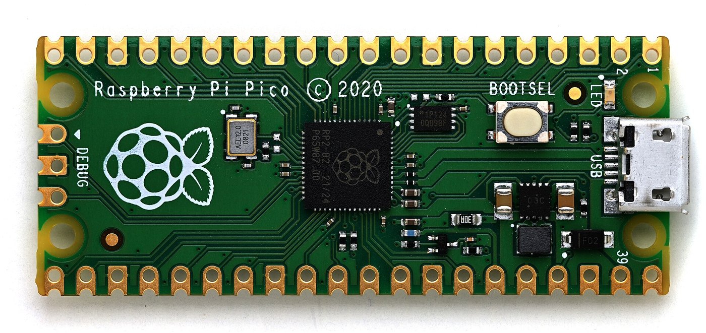
7.1 Two builds, and why
The first six volumes of this dive are the parts. This one assembles them into two things that can be built at a bench in a weekend each:
- a Pico loop interface, which makes any neutral-loop teleprinter, five-level or eight-level, 60 mA or 20 mA, look like an ordinary USB serial port; and
- an optical paper-tape reader, pulled by hand, which turns a tape into a file.
I have a particular use for the first. On Iconic Machines there is a twelve-volume history of PURPLE, the Japanese diplomatic cipher machine broken by the US Army’s Signal Intelligence Service in 1940, and its last volumes design a working replica (PURPLE, Vol 10). The 1941 machine sat between two electric typewriters, one to type on and one to print the result, and the replica’s design gives the printer job to a thermal printer while noting that “a vintage teleprinter is the faithful alternative”. I plan a pair of teletypes for that job: one whose keyboard feeds the replica, one whose printer prints its output. The Teletype Model 15, Vol 8, makes the case for a pair of Model 15s and works out the wiring; this interface is the hardware between them and the replica’s controller, which is itself a Raspberry Pi Pico 2 running its teleprinter lines on PIO.
None of what follows has been built yet, by me or anyone else. It has been designed, drawn, simulated and partly tested in software, and the status section at the end of each build says exactly how far. Check every row of the parts lists against the schematic before ordering, and expect to change something on the bench.
7.2 Build 1: the Pico loop interface
What it does. The computer sees a USB CDC serial port; any terminal program works, and the speed it is set to does not matter. Text from the computer is converted to Baudot (or passed through as ASCII for a Model 33) and sent on the printer loop at the machine’s own speed by a PIO state machine. Characters typed on the machine’s keyboard come back as ASCII. The interface tracks LTRS and FIGS, wraps lines, pads carriage returns, switches the motor through an external relay, and can pass bytes through raw for punching tape.
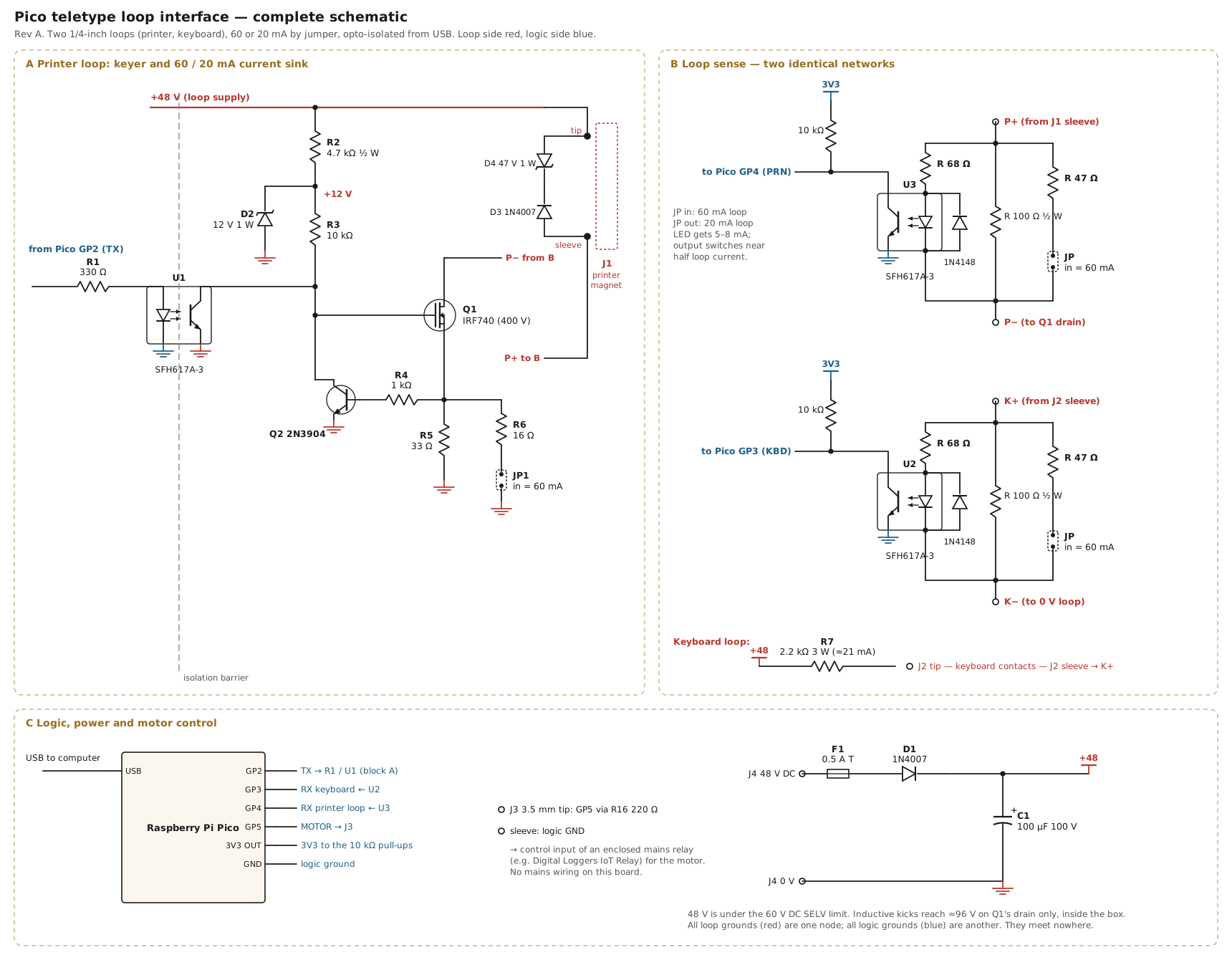
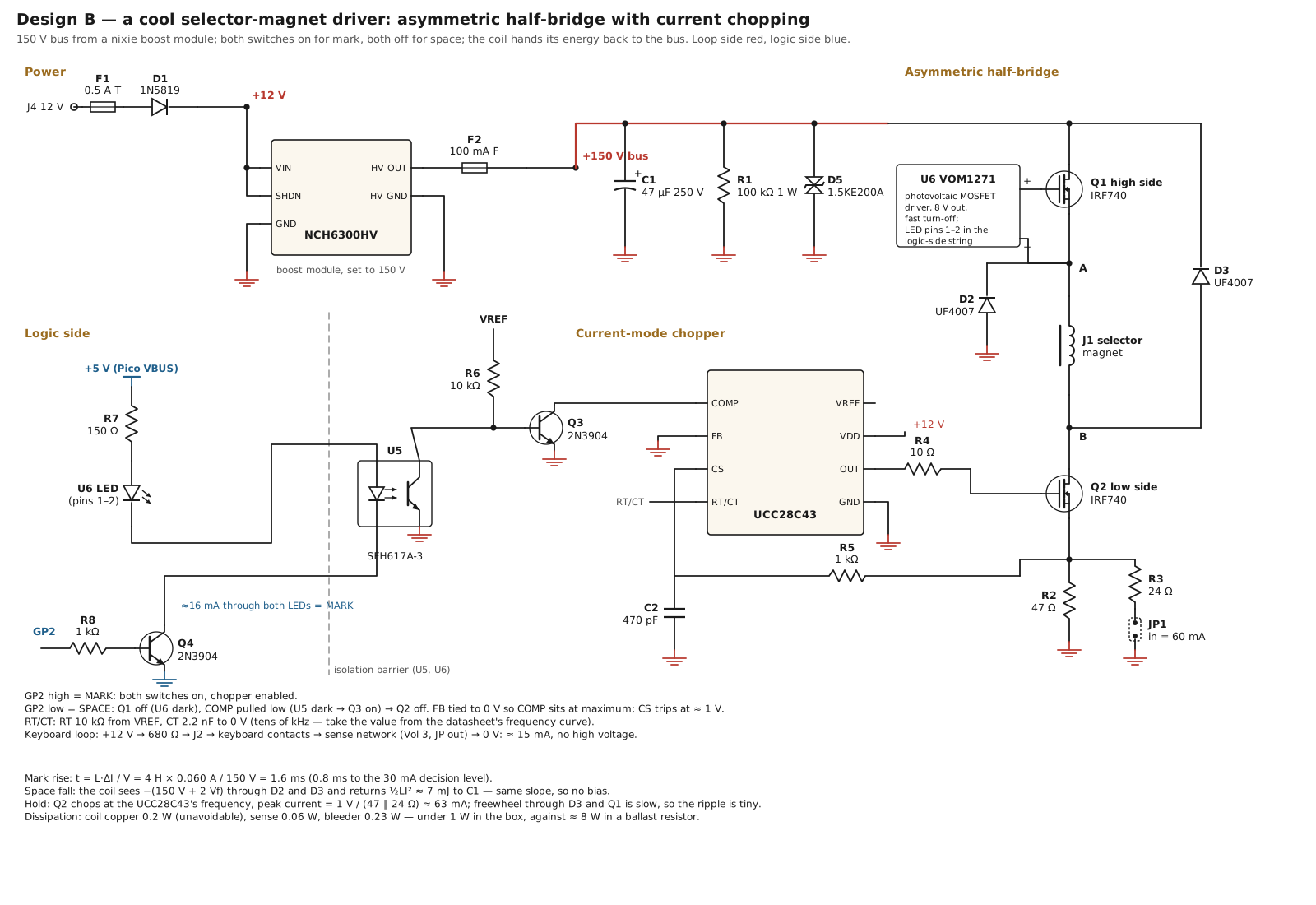
Choose a driver. Block A is Vol 2’s Design A, a 48 V constant-current sink: two transistors, a handful of resistors, 2.5 W into the case. Vol 2’s Design B, the asymmetric half-bridge, replaces block A (and the 48 V adapter) when a cool, small driver is wanted; it runs from 12 V, dissipates under a watt, and keys the magnet faster and more symmetrically, at the cost of about twenty more parts and a 150 V bus inside the box. Blocks B and C are the same for both, except that Design B’s keyboard loop runs from 12 V through 680 Ω. The firmware supports either with one command.
7.2.1 Parts
The full list follows, generated from the same file as the printable PDF at the end of this volume, so the two agree. The PDF adds suppliers, alternates and tick boxes for ordering, checking and fitting.
Pico teletype loop interface, Rev A
Table 1 — Pico teletype loop interface, Rev A
| Qty | Ref | Part | Specification | Part number |
|---|---|---|---|---|
| Logic | ||||
| 1 | — | Raspberry Pi Pico | RP2040, USB, 3.3 V logic | SC0915 |
| 1 | R1 | Resistor 330 Ω | ¼ W 1 % metal film — U1 LED current ≈6 mA | Yageo MFR-25FBF52-330R |
| 2 | R11, R15 | Resistor 10 kΩ | ¼ W 1 % — sense-output pull-ups to 3V3 | Yageo MFR-25FBF52-10K |
| 1 | R16 | Resistor 220 Ω | ¼ W — GP5 to J3 tip (motor relay) | Yageo MFR-25FBF52-220R |
| Isolation | ||||
| 3 | U1, U2, U3 | Optocoupler | phototransistor, CTR 100–200 % at 10 mA, 5.3 kV, DIP-4 | Vishay SFH617A-3 |
| Printer-loop keyer and current sink (block A) | ||||
| 1 | Q1 | N-MOSFET 400 V | TO-220, linear duty ≈2.5 W at 60 mA — bolt to the case | Vishay IRF740PBF |
| 1 | Q2 | NPN transistor | current-sense, TO-92 | onsemi 2N3904BU |
| 1 | R2 | Resistor 4.7 kΩ | ½ W — feeds the 12 V gate rail from +48 V | Yageo MFR50SFTE52-4K7 |
| 1 | D2 | Zener 12 V | 1 W, DO-41 — gate rail | onsemi 1N4742A |
| 1 | R3 | Resistor 10 kΩ | ¼ W — gate pull-up | Yageo MFR-25FBF52-10K |
| 1 | R4 | Resistor 1 kΩ | ¼ W — Q2 base | Yageo MFR-25FBF52-1K |
| 1 | R5 | Resistor 33 Ω | ½ W 1 % — sets 20 mA (0.65 V / 33 Ω) | Yageo MFR50SFTE52-33R |
| 1 | R6 | Resistor 16 Ω | ½ W 1 % — with JP1 in, 33 ∥ 16 Ω sets 60 mA | Yageo MFR50SFTE52-16R |
| 1 | D3 | Rectifier diode | 1 A 1000 V — clamp | onsemi 1N4007 |
| 1 | D4 | Zener 47 V | 1 W, DO-41 — releases the magnet at ≈48 V | onsemi 1N4756A |
| Loop sense networks (block B, two identical) | ||||
| 2 | R8, R12 | Resistor 100 Ω | ½ W 1 % — sense resistor | Yageo MFR50SFTE52-100R |
| 2 | R9, R13 | Resistor 47 Ω | ¼ W — in parallel via JP2/JP3 for 60 mA | Yageo MFR-25FBF52-47R |
| 2 | R10, R14 | Resistor 68 Ω | ¼ W — opto LED series resistor | Yageo MFR-25FBF52-68R |
| 2 | D5, D6 | Signal diode | reverse protection across the opto LED | onsemi 1N4148 |
| 1 | R7 | Resistor 2.2 kΩ 3 W | metal oxide — keyboard loop, ≈21 mA, dissipates ≈1 W | Yageo RSF3WSJT-73-2K2 |
| Power | ||||
| 1 | — | 48 V DC adapter | 25 W, 0.52 A, 2.1 × 5.5 mm centre-positive plug | Mean Well GST25A48-P1J |
| 1 | J4 | DC power jack | 2.1 mm pin, panel mount | Switchcraft 721A |
| 1 | F1 | Fuse 0.5 A slow | 5 × 20 mm, time-lag | Littelfuse 0218.500MXP |
| 1 | D1 | Rectifier diode | reverse-polarity protection | onsemi 1N4007 |
| 1 | C1 | Electrolytic 100 µF 100 V | radial | Nichicon UVR2A101MPD |
| Connectors, hardware, motor control | ||||
| 2 | J1, J2 | 1/4-inch phone jack | 2-conductor (tip/sleeve), open frame | Switchcraft 11 |
| 1 | J3 | 3.5 mm jack | motor-relay control output | CUI Devices SJ1-3523N |
| 3 | JP1–JP3 | 2-pin header + shunt | 0.1 in | Sullins PRPC040SAAN-RC + SPC02SYAN |
| 1 | — | TO-220 insulating kit | Thermalsil pad, shoulder washer, screw | Boyd 4880SG |
| 1 | — | Enclosure | die-cast aluminium, 119 × 94 × 34 mm — also Q1’s heatsink | Hammond 1590BB |
| 1 | — | Perfboard | 0.1 in, about 80 × 60 mm | — |
| 1 | — | Enclosed mains relay for the motor | 3–48 V DC control input, four outlets | Digital Loggers IoT Relay II |
| Option: Design B asymmetric half-bridge driver (replaces block A and the 48 V adapter) | ||||
| 1 | — | 12 V DC adapter | 25 W, 2.1 × 5.5 mm centre-positive | Mean Well GST25A12-P1J |
| 1 | — | HV boost module | 3.7–15 V in, 100–230 V adjustable out — set to 150 V | Omnixie NCH6300HV |
| 1 | D1 | Schottky diode | 1 A 40 V — 12 V reverse protection | onsemi 1N5819 |
| 1 | F1 | Fuse 0.5 A slow | 5 × 20 mm | Littelfuse 0218.500MXP |
| 1 | F2 | Fuse 100 mA fast | 5 × 20 mm, bus | Littelfuse 0217.100MXP |
| 1 | C1 | Electrolytic 47 µF 250 V | bus capacitor, radial | Nichicon UVR2E470MHD |
| 1 | R1 | Resistor 100 kΩ 1 W | bus bleeder | Yageo RSF100JB-73-100K |
| 1 | D5 | TVS 1.5KE200A | 171 V standoff — bus clamp | Littelfuse 1.5KE200A |
| 2 | Q1, Q2 | N-MOSFET 400 V | TO-220 — high and low side; no heatsink needed | Vishay IRF740PBF |
| 2 | D2, D3 | Ultrafast diode | 1000 V 1 A, 75 ns — energy-return diodes | Vishay UF4007-E3/54 |
| 1 | U6 | Photovoltaic MOSFET driver | 8.4 V open-circuit, fast turn-off, SOP-4 — high-side gate | Vishay VOM1271T |
| 1 | U1 | Current-mode PWM controller | near-100 % duty, CS ≈ 1 V, PDIP-8 | Texas Instruments UCC28C43P |
| 1 | U5 | Optocoupler | DIP-4 — COMP shutdown | Vishay SFH617A-3 |
| 2 | Q3, Q4 | NPN transistor | TO-92 — COMP pull-down; LED driver | onsemi 2N3904BU |
| 1 | R2 | Resistor 47 Ω | ½ W 1 % — sense, 20 mA | Yageo MFR50SFTE52-47R |
| 1 | R3 | Resistor 24 Ω | ½ W 1 % — with JP1, 63 mA | Yageo MFR50SFTE52-24R |
| 1 | R4 | Resistor 10 Ω | ¼ W — gate | Yageo MFR-25FBF52-10R |
| 1 | R5 | Resistor 1 kΩ | ¼ W — CS filter | Yageo MFR-25FBF52-1K |
| 1 | C2 | Capacitor 470 pF | C0G, 50 V — CS filter | — |
| 2 | RT, R6 | Resistor 10 kΩ | ¼ W — oscillator, Q3 bias | Yageo MFR-25FBF52-10K |
| 1 | CT | Capacitor 2.2 nF | C0G or film — sets frequency (check the datasheet curve) | — |
| 2 | — | Capacitor 0.1 µF + 1 µF | VREF and VDD bypass | KEMET C320C104K5R5TA |
| 1 | R7 | Resistor 150 Ω | ¼ W — LED string ≈16 mA | Yageo MFR-25FBF52-150R |
| 1 | R8 | Resistor 1 kΩ | ¼ W — Q4 base | Yageo MFR-25FBF52-1K |
| 1 | — | Resistor 680 Ω | ½ W — keyboard loop from 12 V, ≈15 mA | Yageo MFR50SFTE52-680R |
7.2.2 Construction
- Two zones. Lay the perfboard out with a clear line through the middle of the three optocouplers: loop side on one side, Pico side on the other, nothing crossing but the optos. Leave the strip of board under the optos empty. Vol 3 explains why.
- Q1 on the case. Bolt Design A’s Q1 to the wall of the Hammond 1590BB through the Boyd 4880SG insulator kit, and check with an ohmmeter that the tab is not connected to the case before power goes anywhere near it. Keep Q2 at the other end of the board: its base-emitter voltage sets the current, and heat shifts it (Vol 2).
- R7 off the board. The 2.2 kΩ keyboard-loop resistor dissipates about a watt continuously; mount it on its leads, clear of everything.
- Jacks. Two 1/4-inch jacks for the loops, labelled PRINTER (J1) and KEYBOARD (J2), a 3.5 mm jack for the motor relay, and the 2.1 mm power jack. Quarter-inch cables are the traditional teletype loop connector and are still made by the mile.
- Meter jack. A pair of terminals in series with the printer loop, normally shorted by a link, so that a milliammeter can be inserted to set and check the current.
7.2.3 Firmware
The firmware is in 03-outputs/firmware/pico_loop/: main.c, the Baudot tables in baudot.c, the two PIO programs in loop.pio, and a CMakeLists.txt for the standard Raspberry Pi pico-sdk build:
export PICO_SDK_PATH=/path/to/pico-sdk
cp $PICO_SDK_PATH/external/pico_sdk_import.cmake .
mkdir build && cd build && cmake .. -DPICO_BOARD=pico      # or pico2
make                                                        # -> pico_loop.uf2
Hold BOOTSEL, plug in the Pico, and copy pico_loop.uf2 to the drive that appears.
The PIO programs are described in Vol 4. Both run at 64 state-machine cycles per element, so changing speed is a change of clock divider and nothing else. The transmit program takes one 32-bit word per character, describing the frame in half-elements, so 5-bit Baudot with 1.5 stop units and 8-bit ASCII with two stop bits use the same four instructions. The receive program samples at the centre of each element and ignores start elements that vanish within half an element, which rejects contact bounce.
Settings are changed by typing a line that starts with two tildes:
Table 2 — Settings are changed by typing a line that starts with two tildes
| Command | Effect |
|---|---|
~~show | print the current settings and the framing-error count |
~~baud 45.45 | line speed: 45.45, 50, 56.88, 74.2 or any value from 30 to 300 |
~~baudot / ~~ascii | five-bit Baudot (default) or eight-bit ASCII at 110 baud for a Model 33 |
~~ustty / ~~ita2 | the figures table the machine’s type box carries (Vol 4) |
~~uos on / off | assume unshift-on-space (default on) |
~~echo on / off | print the keyboard’s characters locally in full duplex (default on) |
~~half on / off | keyboard and printer in one series loop on J1; ignore the interface’s own sending |
~~width 72 | characters per line before an automatic CR LF |
~~motor auto / on / off | motor relay: on when there is traffic, off after a minute of silence |
~~raw on | pass bytes straight through as codes, for punching tape; three RS (0x1E) bytes leave raw mode |
~~txinv on / off | output polarity: on for Design A (default), off for Design B |
7.2.4 Bring-up
- Logic only. No loop power. Plug in USB, open a terminal on the port (
/dev/ttyACM0on Linux), type~~show. The settings should print. - The loop on a resistor. Connect the 48 V adapter. Put a 470 Ω 5 W resistor and a milliammeter in series on J1 instead of a machine. The meter should read 60 mA with JP1 in, 20 mA with it out, and should not change when you type nothing: the line idles marking.
- Signal. Type
RYRYRYRYcontinuously. A moving-coil meter should drop to about 32 mA (Vol 1); a battery-powered oscilloscope across a 10 Ω resistor in the loop should show 22 ms elements with clean edges. On Design A, the drain of Q1 should rise to about 96 V at each space and stop there. - Keyboard loop. Short J2’s tip to its sleeve through a switch and press it in a rhythm: nothing should print, but
~~showshould count framing errors, which proves that U2 sees the loop. A real keyboard will produce characters. - The machine. Strap the selector magnet for the loop current (Vol 1), bypass any polar relay, and wire the keyboard and printer to separate jacks. Switch the motor on, send
RYRY, and type on the keyboard. Then take a range (Inside the Teletype Mechanism, Vol 1) and write the result down: it is the number that says whether the interface is good.
7.2.5 Using it
- As a terminal. Any terminal program; or a Linux login with
agetty -L 9600 ttyACM0 tty33(Vol 4). - For the news. The ITTY pipeline of Vol 5 ends in
/dev/ttyACM0;fldigi_bridge.py /dev/ttyACM0prints whatever fldigi decodes off the air. - For tape. On a Model 33,
~~asciiand~~raw on, then send DC2, a NUL leader, the bytes, a NUL trailer and DC4 (Vol 6). On a Baudot reperforator,~~raw onand send the five-bit codes. - For the PURPLE pair. The replica’s controller can talk to the machines through two of these interfaces’ front ends, or use their PIO programs directly on its own Pico 2: the keyboard machine’s loop on a sense input, the printer machine’s loop on a keyer.
7.2.6 Status
Built: no. Tested so far: the PIO programs, assembled and run in an RP2040 PIO emulator (test_pio.py: the letter Y transmitted with correct timing; the letter R received through a deliberate glitch); the C Baudot tables against the Python ones, character for character; main.c syntax-checked against stub headers (not yet compiled against the real pico-sdk); the loop designs simulated (loop_sim.py); the termios2 sender run on a pseudo-terminal; the AFSK decoder run on the live ITTY stream.
7.3 Build 2: an optical tape reader
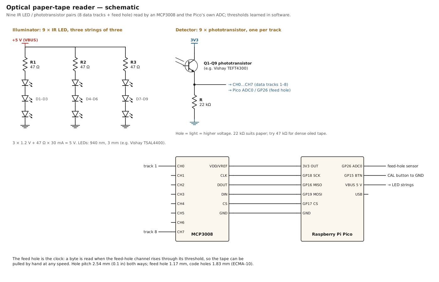
What it does. Pull a 5-level or 8-level tape through it by hand, and each row comes out of the USB port as a byte, or as decoded Baudot text. The feed hole is the clock, so the speed of the pull does not matter.
7.3.1 Parts
Optical paper-tape reader, Rev A
Table 3 — Optical paper-tape reader, Rev A
| Qty | Ref | Part | Specification | Part number |
|---|---|---|---|---|
| Electronics | ||||
| 1 | — | Raspberry Pi Pico | MicroPython firmware main.py | SC0915 |
| 1 | U1 | 8-channel 10-bit ADC | SPI, DIP-16, runs at 3.3 V | Microchip MCP3008-I/P |
| 10 | D1–D9 (+1 spare) | IR LED 940 nm | 3 mm (T-1), narrow beam | Vishay TSAL4400 |
| 10 | Q1–Q9 (+1 spare) | Phototransistor | 3 mm (T-1), daylight filter | Vishay TEFT4300 |
| 3 | R1–R3 | Resistor 47 Ω | ¼ W — LED strings ≈30 mA | Yageo MFR-25FBF52-47R |
| 9 | R (×9) | Resistor 22 kΩ | ¼ W — phototransistor loads; try 47 kΩ for dense tape | Yageo MFR-25FBF52-22K |
| 1 | C1 | Capacitor 0.1 µF | ceramic, MCP3008 decoupling | KEMET C320C104K5R5TA |
| 1 | SW1 | Pushbutton | momentary, CAL | Omron B3F-1000 |
| Mechanics | ||||
| 1 | — | Tape guide and aperture plates | two plates with a 0.1 in row of 1.5 mm holes, 1 in and 11/16 in channels | — |
| 1 | — | Perfboard | 0.1 in | — |
7.3.2 Mechanics
The electronics are the easy part; the mechanics decide whether it reads. Two plates sandwich the tape: an illuminator plate with the nine LEDs, and a detector plate with the nine phototransistors behind an aperture, a row of nine holes no larger than about 1.5 mm, on a 2.54 mm pitch, with the feed-hole aperture in the fourth position counting from the reference edge for 8-level tape. The aperture is what stops each sensor seeing its neighbour’s hole; Müller’s e-basteln design makes its apertures from thin PCB, and that is a good model. Spacers set a channel wide enough for 1-inch tape, with a removable guide strip for 11/16-inch tape that puts its feed track over the same sensor; its five levels then fall on sensors 2 to 6, and the firmware shifts them down when LEVELS = 5. The tape should slide flat, with no sprocket and no tension.
7.3.3 Firmware and use
03-outputs/firmware/tape_reader/main.py is MicroPython. Copy it to the Pico as main.py. Set LEVELS (5 or 8) and MODE (raw, hex or baudot) at the top.
Calibrate once for each kind of tape: hold the CAL button while pulling about 30 cm of punched tape through, then release. The firmware records the darkest and brightest reading on every channel and puts each threshold midway; they are saved in thresholds.json and survive power-off. Read by pulling the tape steadily. While the feed hole is in view, the firmware keeps the peak reading of each data channel; when the feed hole has passed, it compares the peaks with the thresholds and emits one row. On Linux:
stty -F /dev/ttyACM0 raw -echo
cat /dev/ttyACM0 > tape.bin            # MODE = "raw": one byte per row
python3 tape.py svg tape.bin --levels 8 tape.svg      # look at what was read
For a fragile tape, scan it instead and use tape.py decode (Vol 6).
7.3.4 Status
Built: no. The Baudot tables in main.py were checked against baudot.py; the rest is untested. The aperture plates are the part most likely to need a second attempt.
7.4 What the two builds share
Both builds are small, and both are deliberately plain. Nothing in either needs a part that is hard to buy, and nothing in the interface needs a voltage that can hurt anyone outside the box. Both are built around the same idea that runs through this whole dive: a teletype is a serial device with a strict but simple protocol, and a few dollars of modern parts can speak that protocol exactly, without the 120-volt supply and the hot resistors that made the job dangerous for fifty years.
When the PURPLE pair arrives, the interface will be the first thing to connect and the ITTY news the first thing to print. I expect to come back and correct this volume once both have happened.
7.5 Printable Bill of Materials
The parts lists above as printable PDFs, with ordering, in-hand and fitted tick boxes, part numbers, alternates and suppliers:
- Pico teletype loop interface BOM (PDF) — Design A, with Design B as an optional last group.
- Optical paper-tape reader BOM (PDF)
7.5.1 Sources (Vol 7)
- PURPLE replica and its printer (“a vintage teleprinter is the faithful alternative”): PURPLE, Vol 10, Iconic Machines. https://iconic-machines.fubsypoly.com/purple/vol-10/ · the Model 15 pair: The Teletype Model 15, Vol 8. https://dots-and-dashes.fubsypoly.com/teletype-model-15/
- Raspberry Pi Pico (SC0915) and Pico 2 (SC1631); PIO and UART divisors: RP2040 Datasheet. https://datasheets.raspberrypi.com/rp2040/rp2040-datasheet.pdf ; pico-sdk https://github.com/raspberrypi/pico-sdk
- MCP3008 8-channel 10-bit SPI ADC: Microchip datasheet. TSAL4400 (940 nm IR LED) and TEFT4300 (phototransistor): Vishay datasheets, https://www.vishay.com/en/product/81549
- e-basteln reader (aperture plates, calibration, Pro Micro): https://e-basteln.de/computing/papertape/building/
- Part numbers and suppliers: see the printable BOMs; distributor listings read 3 November 2026 (Mean Well GST25A48-P1J, Digi-Key 1866-2095-ND; Raspberry Pi SC0915 and SC1631; Boyd 4880SG; Switchcraft 721A; Digital Loggers IoT Relay II, https://www.digital-loggers.com/iot2faqs.html; Omnixie NCH6300HV datasheet).
- Code and drawings:
03-outputs/firmware/pico_loop/(main.c, baudot.c/.h, loop.pio, CMakeLists.txt, test_pio.py);03-outputs/firmware/tape_reader/main.py;03-outputs/tools/(draw_schematics.py, loop_sim.py, tape.py, baudot.py, afsk.py, tty_send.py, fldigi_bridge.py); BOM sources03-outputs/bom/*.json, rendered by the sharedbom_pdf.py.