Interfacing Teletypes and Paper Tape · Volume 1
Interfacing Teletypes and Paper Tape — Vol 1: The Current Loop
Why a teleprinter signals with current instead of voltage, neutral and polar loops, 60 mA and 20 mA, what the selector magnet's inductance does to every edge, the arithmetic of a loop, how to measure one, and how not to be hurt by it.
1.1 The two wires behind the clatter
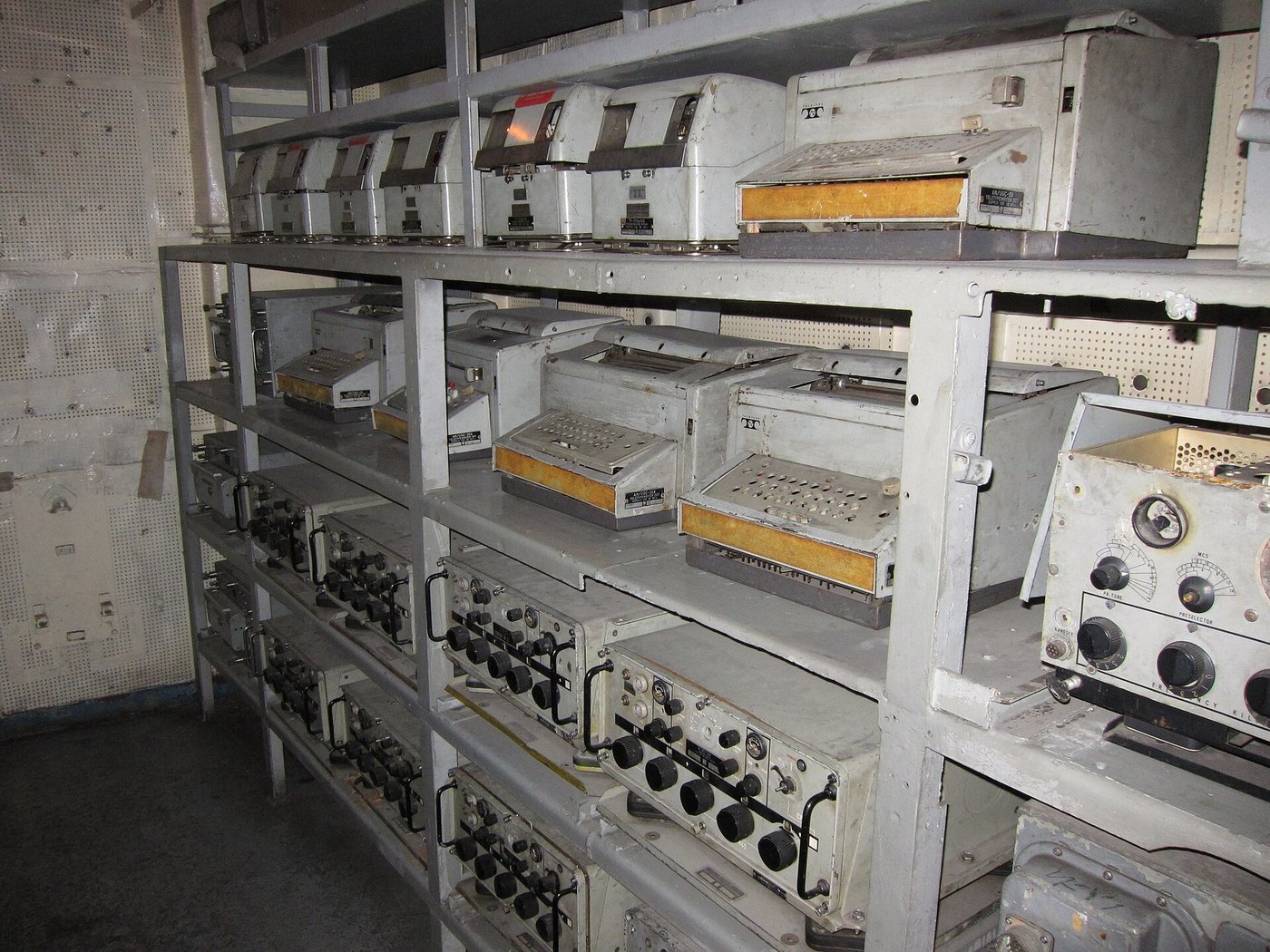
In my father’s shack in the late 1960s, the teletypes were the thing to watch, chattering away with pink tape spooling out of them. What connected the machine to the radio was a pair of wires, and a pair of wires is easy to overlook.
As an electronics engineer I now think those two wires are the most interesting thing in the whole system, because they carry a signal that no modern interface uses. A teleprinter does not listen for a voltage. It listens for a current, typically 60 milliamperes flowing in a series circuit, and it reads a character from the pattern of that current switching on and off. Every problem of connecting a teletype to anything newer than about 1970 starts here.
The sibling dives have already said the short version. Restoring a Teletype, Vol 2, explains why a teleprinter cannot be plugged into a serial port. Making the Parts That No Longer Exist, Vol 2, describes the DeRamp regenerative interface. The Teletype Model 15, Vol 6, works through the loop for that one machine. This dive is the general case. It covers any start-stop machine on a neutral or polar loop, five-level or eight-level, and it goes far enough into the electronics to design an interface from first principles. It finishes with two builds: a Raspberry Pi Pico loop interface and an optical paper-tape reader (Vol 7).
I do not own a teletype yet. I plan a pair of them for the PURPLE cipher-machine replica described on Iconic Machines, which is one reason this dive exists. Everything here is written so that it can be checked against the documents it cites before any of it is soldered.
1.2 Why a current and not a voltage
The teleprinter inherited its signalling from the telegraph, and the telegraph was a series circuit. A battery at one end, a key, many miles of iron wire, the sounders and relays of every station on the line, and a return through the earth or a second wire: one loop, one current, everything in series.
A series circuit has a property that made it the right choice for a line of unknown and changing length. The current is the same at every point in it. Whatever the resistance of the wire, if the battery is set to drive the correct current, every magnet in the loop receives the same pull. Add a station, and its magnet joins the series string; adjust the battery or a rheostat, and the current is right again. The receiving instruments only care about ampere-turns, and a current loop delivers ampere-turns directly.
The teleprinter kept the idea and standardised the current. The selector magnet of a Model 15 or Model 28 is a large electromagnet with an iron armature, and it is designed to operate at 60 mA. Later machines, and most machines built to work with computers, were designed for 20 mA. The keyboard of the machine is a set of contacts in the same loop. When the operator types, those contacts break and make the loop current in the pattern of the character, and every selector magnet in the loop, the sender’s own included, follows.
Three consequences follow, and they are worth keeping in mind for the rest of the dive:
- Mark is current; space is no current. The convention is the telegraph’s. A closed key is a mark.
- The line idles marking. With nobody typing, full current flows continuously and the selector armature sits pulled up. The machine waits.
- A broken loop is a continuous space. The selector reads an open circuit as an endless stream of start elements followed by all-space characters, and the machine “runs open”, hammering away at nothing. Restoring a Teletype, Vol 2, describes the noise.
That last point has a practical use. A deliberate, long space on the line is the break signal. A Model 33 keyboard has a BREAK key that does exactly that (Vol 4), and on a line it is how one station interrupts another.
1.3 Neutral and polar loops
What the dive has described so far is a neutral loop: current one way, or no current. It is the loop of almost every hobby installation and of the machines a reader is likely to own.
The alternative is a polar loop, in which the current never stops. It flows one way for mark and the other way for space. The receiver is a polar relay or a polar magnet, a magnetic circuit with a permanent bias that moves one way or the other depending on the direction of the current, and the sending end is a pole changer, a contact that connects the line to the positive or the negative side of a centre-tapped battery.
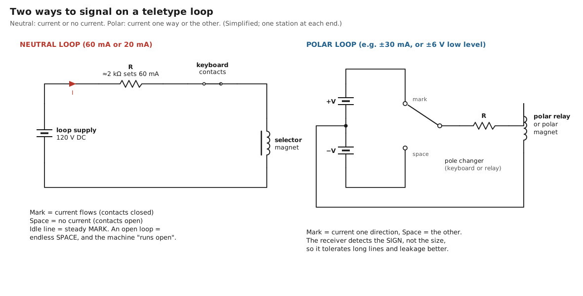
Polar working earns its complexity on long lines. In a neutral loop, the receiving magnet’s decision depends on the size of the current: is it above or below the level at which the armature pulls in? Line leakage, line capacitance and a drifting battery all move the current, and every movement shifts the instant at which the magnet decides. The result is bias distortion, a systematic lengthening or shortening of every marking element. A polar receiver decides on the sign of the current, and the sign is far harder to disturb than the size. Teletype’s own documents treat polar operation as a standard option: the 1965 TP177010 selector-magnet driver described below accepts “neutral signals of either 0.020 or 0.060 ampere or polar signals of up to 0.030 ampere”, and the Model 33’s call control unit has polar-to-neutral converting circuits for machines modified for polar lines.
The military took the idea furthest. Shipboard and station equipment from the 1960s onward used low-level polar signalling, about plus and minus 6 volts, between equipment in the same building; the US Navy’s PP-6521/FGC was a dedicated supply for exactly those ±6 V signals. Low-level polar is close to RS-232 in spirit, and it is one reason late military terminal units offer an RS-232 output beside their loop.
For an interface designer, the practical rule is simple. A hobby machine will almost always be on a neutral loop, and any polar relay inside it can be bypassed for neutral working. The Teletype Model 15, Vol 6, gives the terminal changes for that machine. Everything after this section assumes neutral working unless it says otherwise.
1.4 Sixty milliamperes and twenty
Teletype built magnets for two current levels, and it is worth understanding why, because it decides how a given machine must be strapped before it is connected to anything.
Holding magnets and pulling magnets. In a Model 15, the selector magnet either holds the armature against a spring until the current stops, or pulls it in from rest when the current starts. Restoration notes put the two types at about 200–220 ohms for a pulling magnet and 50–55 ohms for a holding magnet with its two coils in parallel (DeRamp manual). The holding magnet’s two coils are the key to the current level. Wired in parallel, the magnet wants 60 mA; wired in series, the same ampere-turns arrive with 30 mA through twice the turns, and the series strapping is what lets such a magnet run on a lower-current line. Collector discussions summarise the rule as series for low-current loops, parallel for 60 mA, and pulling magnets always in series at 60 mA (PICList thread, below). Check the data plate and the strapping of the actual machine; The Teletype Model 15, Vol 6, shows one with its switch set to “Parallel (60 mA)”.
Electronic receivers. By the 1960s, Teletype had stopped asking the line to drive the magnet directly. The Model 33’s selector is fed by a transistor driver inside the call control unit, and its technical description is unusually clear about what it does: the driver “delivers marking signals of 0.500 ampere and spacing signals of essentially 0 ampere to the associated selector magnet”, and the signals “trigger the selector magnet driver circuit at about half the current level” of the line. The line itself can be 0.020 or 0.060 ampere. The Model 33’s technical data then give the operating margins the machine was designed for:
Table 1 — Electronic receivers. By the 1960s, Teletype had stopped asking the line to drive the magnet directly. The Model 33's selector is fed by a transistor driver inside the call control unit, and its technical description is unusually clear about what it does: the driver "delivers marking signals of 0.500 ampere and spacing signals of essentially 0 ampere to the associated selector magnet", and the signals "trigger the selector magnet driver circuit at about half the current level" of the line. The line itself can be 0.020 or 0.060 ampere. The Model 33's technical data then give the operating margins the machine was designed for
| Line type | Current | Supply | Load |
|---|---|---|---|
| Long telegraph loops | 0.015 to 0.070 A | 48 to 240 V DC | inductive |
| Short telegraph loops | 0.058 to 0.072 A | 16 to 22 V DC | resistive |
Source: Teletype Section 574-100-102, 32 and 33 Teletypewriter Sets — Description, technical data, in Bulletin 273B (1964).
Those two rows say something important. A long telegraph loop with real line inductance needed real voltage. A short local loop, with nothing in it but a driver input that is “essentially resistive”, worked with 16 to 22 volts. The high voltage of a classic teletype loop exists to drive an inductive load quickly. Take the inductance away, and the voltage requirement disappears with it. The whole of Vol 2 rests on that observation.
The selector-magnet driver. The cleanest statement of the problem, and of its solution, is a small 1965 Teletype part, the TP177010 electronic selector magnet driver. It was “designed specifically to drive one 28 selector magnet or one 15 selector holding magnet”, and when “used in place of a line relay (such as the Western Electric 255A)” it was claimed to “provide improved operation, greater reliability and reduced maintenance”. Its input accepts 20 mA or 60 mA neutral or 30 mA polar and switches at the midpoint of the line current (10 mA or 30 mA). Its output is always 60 mA. Its own supply was only about 40 volts, and its description explains how it still pulls the magnet in fast: on each space-to-mark transition it “places essentially the full supply potential across the coils”, so that the current “aims at” a value “much higher than the desired 0.060 a.”, and then “adds resistance to maintain the operating current”. On the mark-to-space transition “a controlled discharge circuit … rapidly dissipates the coil’s energy without developing any high reverse voltage transients”.
That is a constant-current driver with a forced rise and a clamped fall, built from five transistors in 1965. The modern design in Vol 2 does the same thing with two.
1.5 The magnet is an inductor
Everything difficult about a teletype loop comes from one number. A selector magnet is a coil wound on an iron core, and its inductance is large. The figure most often quoted for a Model 15 holding magnet is about 4 henries (John Nagle, via Trammell Hudson’s notes), with a coil resistance of about 55 ohms.
An inductor opposes any change in its current. Connect a voltage V across a coil of inductance L and total circuit resistance R, and the current does not jump to V/R. It rises along an exponential with time constant
tau = L / Rand reaches 63 per cent of its final value after one time constant, 95 per cent after three. The element the magnet has to follow at 60 words per minute is 22 ms long, and the selector samples it near the middle. The current has to be well established within a few milliseconds of each transition, or every mark arrives late and every space leaves late.
Put the magnet’s own numbers into the formula:
magnet alone:        L / R = 4 H / 55 ohm      =  73 ms   (three whole elements)
12 V supply, 60 mA:  R = 200 ohm,  tau = 4/200  =  20 ms   (one whole element)
120 V supply, 60 mA: R = 2000 ohm, tau = 4/2000 =   2 ms
This is why the classic loop runs at 120 volts. The voltage is not needed to push 60 mA through 55 ohms; 3.3 volts would do that in the steady state. It is needed so that a large series resistance can be used, because the large resistance makes the time constant short. A 120-volt loop wastes nearly all its power in that resistor and has done so since the 1920s.
The other half of the problem is the release. When the loop opens for a space, the energy stored in the magnet, ½ L I², about 7 millijoules at 60 mA, has to go somewhere. If nothing is provided, the collapsing field raises the voltage across whatever opened the circuit until something breaks down: an arc across keyboard contacts, or a transistor junction. If a plain diode is put across the coil to catch that energy, the current circulates through the diode and the coil’s own 55 ohms and decays with the coil’s own 73 ms time constant. The magnet then never releases in time for the next element. The figure below shows that failure with the other cases.
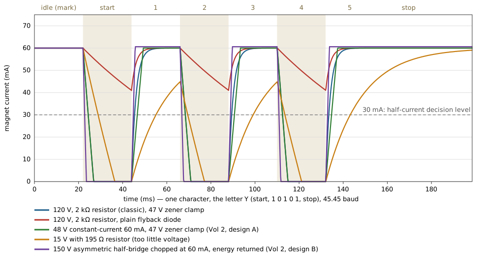
The script that drew the figure, 03-outputs/tools/loop_sim.py, also measures how long each design takes to cross the half-current level after each transition, because that is what decides the timing the selector sees:
Table 2 — The script that drew the figure, 03-outputs/tools/loopsim.py, also measures how long each design takes to cross the half-current level after each transition, because that is what decides the timing the selector sees
| Drive | Make: edge to 30 mA | Break: edge to 30 mA | Bias |
|---|---|---|---|
| 120 V, 2 kΩ, 47 V clamp | 1.36 ms | 2.38 ms | +4.6 % (marks long) |
| 120 V, 2 kΩ, plain diode across the coil | — | never | magnet stuck |
| 48 V constant current, 47 V clamp | 2.60 ms | 2.38 ms | −1.0 % |
| 15 V, 195 Ω | 11.08 ms | 4.61 ms | −29.4 % |
| 150 V half-bridge, chopped at 60 mA, energy returned | 0.80 ms | 0.77 ms | −0.1 % |
Model: L = 4 H, R = 55 Ω, armature motion ignored. Bias = (break delay − make delay) ÷ element length. Useful for comparing designs, not for predicting a particular machine.
Two delays of the same size do no harm. They shift the whole character later by the same amount, and the receiving selector, which restarts its timing at every start element, does not notice. Inside the Teletype Mechanism, Vol 1, shows why: the range finder simply moves the sampling instant. What hurts is a difference between the two delays. That difference lengthens every mark and shortens every space, or the reverse, and it eats directly into the machine’s range, the measurement Restoring a Teletype, Vol 2, uses as its acceptance test. The design target for any loop driver is therefore not “fast” but symmetrical: make and break should take the same time.
1.6 Loop arithmetic
With the physics settled, sizing a classic resistor-limited loop is Ohm’s law and a little care.
One machine, 60 mA, 120 V supply, holding magnet at 55 Ω:
total resistance  = 120 V / 0.060 A           = 2000 ohm
series resistor   = 2000 − 55                  = 1945 ohm   -> 2 kohm, trimmed
power in resistor = 0.060^2 x 1945             = 7.0 W      -> a 25 W part
power in magnet   = 0.060^2 x 55               = 0.2 W
A pulling magnet at 220 Ω needs 1780 Ω. The total is still 2000 Ω, so the time constant is set by the supply, not by the magnet. Two machines in series add their magnets and keyboards: two holding magnets need 1890 Ω. The supply voltage does not change, which is the whole point of a series loop.
A 20 mA loop for a machine with an electronic receiver, such as a Model 33, is a different calculation, because there is no large inductance to fight. The current only has to be inside the margins in the table above. A 24-volt supply and about 1.1 kΩ give 20 mA into a short resistive loop and dissipate under half a watt. Vol 3 uses a constant-current source instead of the resistor, which makes the current independent of what is in the loop.
Wire. At 60 mA the wire does not matter inside a room. A hundred feet of 22 AWG adds about 3 Ω, less than the tolerance of the series resistor.
1.7 Measuring a loop
A loop is easy to measure, and a restorer should measure it before blaming the machine.
- A milliammeter in series reads the loop current directly. The idle line should read 60 mA (or 20 mA). This is why period loop supplies carry a meter on the front panel and why the DeRamp board has a jumper position for one.
- A moving-coil meter on a test pattern averages the current, which gives a quick check of the signal itself. On the RYRY test text, the marking fraction is (3.42 + 4.42) units out of 2 × 7.42, about 53 per cent, so a 60 mA loop sending RYRY should read about 32 mA. A reading far from that suggests distortion or a wrong speed before anything is opened.
- An oscilloscope shows the current waveform, which is the only way to see the rise and fall in the figure above. Measure the voltage across a small sense resistor, 10 Ω gives 0.6 V at 60 mA, but remember that the loop is floating and may sit a hundred volts from earth. Use a battery-powered or differential instrument, or put the sense resistor at a point that is genuinely at the instrument’s ground. Clipping a mains-earthed scope ground lead to an arbitrary point in a loop is a reliable way to short the supply through the scope.
- A range test on the machine (Inside the Teletype Mechanism, Vol 1) is the final arbiter. A good interface gives a wide range; a bad one narrows it.
1.8 Safety
A classic teleprinter loop is the most dangerous part of the hobby, and it is easy to forget because nothing about it looks dangerous.
- The voltage. A 120-volt DC supply sits at the edge of the IEC 61140 definition of extra-low voltage (120 V ripple-free DC) and well above the 60 V DC that touch-safe equipment standards such as AS/NZS 60950.1 use. Vintage terminal units go higher. The HAL ST-6 and ST-5000 manuals specify an internal 175 V, 60 mA loop supply and print the warning in capitals: “THE 175 VOLT LOOP POWER SUPPLY CAN CAUSE A LETHAL ELECTRICAL SHOCK”. DC does not pass through zero a hundred and twenty times a second, so a hand that closes on it can be held.
- The stored energy. A filter capacitor holds its charge after the supply is switched off, and the Model 33 installation manual warns that the tape reader’s “high voltage … will continue until approximately 10 seconds after the tape reader has been disconnected”. Discharge and measure before touching.
- The inductive kick. Open a 60 mA loop with your fingers in it and the magnet’s stored energy comes out as a spike across the gap. It is a small amount of energy, but the voltage is high and the reflex it provokes near moving machinery is the real hazard.
- Isolation. A loop supply must be isolated from the mains by a transformer, and a loop that touches a computer must be isolated from the computer by optocouplers. The loop then has no reference to earth at all, which is safer, and which is also why the measurement advice above matters.
The modern answers, in Vol 2, keep the high voltage away from fingers. The first is a constant-current loop driven from 48 volts, the voltage the telephone exchange has used for a century. It does the job as well as a 120-volt resistor loop, keeps the steady-state voltage below the 60 V touch-safe level, and leaves the high-voltage transients inside a closed box. The second, like the DeRamp and ttyloopdriver boards, recycles the magnet’s own energy and runs cool.
Next: Vol 2 builds the loop supply, old and new.
1.8.1 Sources (Vol 1)
- TP177010 selector-magnet driver (1965): input 0.020 or 0.060 A neutral or up to 0.030 A polar, output 0.060 A, for one Model 28 magnet or one Model 15 holding magnet; replaces a Western Electric 255A line relay; switching at the midpoint of the input current; forced rise (“essentially the full supply potential across the coils”) and controlled discharge; nominal −40 V internal supply. Teletype Corp. / Bell System Practices, Section 570-224-100, TP177010 Selector Magnet Driver — Description and Principles of Operation, Issue 1, February 1965. https://navy-radio.com/manuals/tty/570-224-100.pdf (Internet Archive copy).
- Model 32/33 line currents and margins (0.020 or 0.060 A; long loops 0.015–0.070 A at 48–240 V inductive; short loops 0.058–0.072 A at 16–22 V resistive; 8-level 11-unit code for the 33) and the Model 33 selector-magnet driver (0.500 A to the magnet; triggers at about half the line current; polar-to-neutral converting circuits). Teletype Bulletin 273B, Vol 1, Technical Manual, 32 and 33 Teleprinter Sets, November 1964, Sections 574-100-102 and 574-123-101. https://new.vaxbarn.com/pub/pdf/teletype/ ; 574-123-101TC also at https://navy-radio.com/manuals/tty/jh/bsps/bsp/570series/574-123-101TC.pdf
- Model 33 tape-reader power pack warning (“high voltage … approximately 10 seconds”). Teletype Section 574-100-201TC, 32 and 33 Teletypewriter Sets — Installation, Issue 3, July 1964. https://navy-radio.com/manuals/tty/jh/bsps/bsp/570series/574-100-201TC.pdf
- Selector-magnet inductance (about 4 H), 60 mA design current, ~100 V supplies and ~6 W in the resistors. Trammell Hudson, “Model 15 Teletype.” https://trmm.net/Model_15_Teletype/
- 55 Ω selector magnet, 120 V DC loop supply, 2 kΩ 10 W resistor in John Nagle’s interface board. Aetheric Message Machine Company, “Connecting a Teletype Model 15 to a Personal Computer.” https://www.aetherltd.animats.com/connecting.html
- Pulling magnet 200–220 Ω; holding magnet coils in parallel 50–55 Ω; polar relay bypass. Mike Douglas, ASCII/RS-232/AFSK Interface for the Model 15 Teletype, user manual, deramp.com. https://deramp.com/downloads/teletype/Model%2015/loop%20interface%20board/User%20Manual.pdf
- Holding magnets series for 20 mA / parallel for 60 mA, pulling magnets always series at 60 mA — collector discussion, PICList archive, 2013. https://pic.hallikainen.org/piclist/2013/06/28/200947a.txt ⟨secondary; consistent with the DeRamp manual’s resistances⟩
- US Navy loop supplies: PP-6521/FGC for ±6 V low-level signals; 60 mA per loop on TT-23/SG panels; PP-1767 120 V DC 1 A. navy-radio.com, “US Navy Teletype Loop Supplies.” https://navy-radio.com/tty-loop.htm (read through the Internet Archive).
- 175 V, 60 mA loop supplies and the lethal-shock warning. HAL Communications, ST-6 RTTY Demodulator manual and ST-5000 FSK Demodulator/Keyer manual. https://navy-radio.com/rtty/hal/st6/manual/ST6_Manual.pdf ; https://navy-radio.com/rtty/hal/st5000/manual/ST5000_Manual.pdf
- Extra-low voltage limits (IEC 61140: 120 V ripple-free DC; AS/NZS 60950.1: 60 V DC). Wikipedia, “Extra-low voltage.” https://en.wikipedia.org/wiki/Extra-low_voltage
- Simulation and figures:
03-outputs/tools/loop_sim.py,03-outputs/tools/draw_schematics.py(this dive). - Cross-links: Restoring a Teletype, Vol 2; Inside the Teletype Mechanism, Vol 1 (range); Making the Parts That No Longer Exist, Vol 2 (DeRamp); The Teletype Model 15, Vol 6 (https://dots-and-dashes.fubsypoly.com/teletype-model-15/); The Teletype Model 28 (https://dots-and-dashes.fubsypoly.com/teletype-model-28/); PURPLE, Vol 10 (https://iconic-machines.fubsypoly.com/purple/vol-10/).