Interfacing Teletypes and Paper Tape · Volume 3
Interfacing Teletypes and Paper Tape — Vol 3: Talking to a Computer — the Hardware
Sensing a loop with an optocoupler, keying one with a high-voltage transistor or MOSFET, keeping the computer isolated, which USB-serial chips can and cannot do five bits at 45 baud, the ASCII machines' passive loops, and the interfaces that exist today.
3.1 Three jobs and three routes
Restoring a Teletype, Vol 2, lists three incompatibilities between a teleprinter and a computer: a current loop instead of a voltage, Baudot instead of ASCII, and 45.45 baud instead of anything a serial port normally offers. An interface is whatever does those three jobs, and there are only three ways to divide them up.
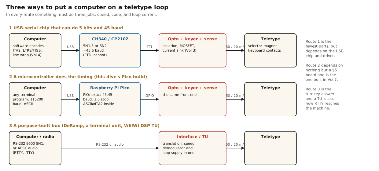
All three routes share one piece of hardware: the front end that touches the loop. It has to sense current in one loop, switch current in another, survive the magnet’s inductive kick, and keep the computer electrically separate from all of it. This volume is about that front end and about the parts on either side of it. Vol 4 is about the software.
3.2 Sensing a loop
The keyboard of a teleprinter is a set of contacts that open and close the loop current. To read it, put something in the loop that responds to the current and reports to the computer without being connected to it. That something is an optocoupler: an infrared LED and a phototransistor in one package, separated by a few millimetres of transparent insulation.
The obvious circuit is to put the opto’s LED straight into the loop. It works, and it has three problems.
- Current. Many optocouplers are rated for 50 or 60 mA of LED current, and a 60 mA loop sits at or above that limit permanently, because the line idles marking. W6IWI’s DSP terminal unit does use an AC-input H11AA1 directly in its 60 mA loop, and notes that the opto transitions near 27 mA, but that leaves little margin.
- Threshold. The LED begins to conduct at a fraction of a milliampere, so the opto reports “mark” at the first trickle of current. A loop receiver should decide at about half the loop current, as Teletype’s own receivers did: the 1965 TP177010 driver switches at 10 mA on a 20 mA line and 30 mA on a 60 mA line, and the Model 33’s driver at “about half the current level” (Vol 1).
- Polarity. Connected the wrong way round, a single LED blocks the loop entirely.
The sense network used in this dive fixes all three with four passive parts.
loop current -->  R_s (100 ohm, or 100 || 47 = 32 ohm for 60 mA)  --> loop
                  in parallel with:  68 ohm + opto LED, and a 1N4148 reversed across the LED
The loop current flows through R_s. The voltage across it drives the LED through 68 Ω. Solving for the LED current with an LED forward voltage of about 1.15 V:
Table 1 — The loop current flows through Rs. The voltage across it drives the LED through 68 Ω. Solving for the LED current with an LED forward voltage of about 1.15 V
| Loop | R_s | Voltage across R_s at full current | LED current | Loop current at which the LED reaches ~0.5 mA |
|---|---|---|---|---|
| 20 mA | 100 Ω | 1.49 V | ≈ 5 mA | ≈ 11 mA |
| 60 mA (jumper in) | 32 Ω | 1.67 V | ≈ 7.7 mA | ≈ 35 mA |
The LED never sees more than 8 mA, the output switches somewhere around half to two-thirds of the loop current, and the reversed 1N4148 carries the loop if it is wired backwards, so the machine still works and the computer simply sees nothing. The network drops less than 2 V, which any loop supply can spare.
The output side. The phototransistor needs to sink the computer input’s pull-up current. With a 10 kΩ pull-up to 3.3 V, that is 0.33 mA. A Vishay SFH617A-3 has a current transfer ratio of 100 to 200 per cent at 10 mA, so 5 to 8 mA of LED current gives several milliamperes of collector capability, ten times what is needed. Cheaper PC817-family parts, with a guaranteed CTR of 50 per cent, also work at these currents.
Which way up. Wired with the phototransistor’s emitter to ground and its collector to a pulled-up input, the input reads low on mark. That is the opposite of a UART’s convention, where the idle line is high. There are two remedies: wire the transistor as an emitter follower instead (collector to the supply, emitter to the input with a pull-down), which reads high on mark, or invert the input inside the microcontroller. The Pico interface does the latter, because the RP2040’s GPIO has an input-inversion switch.
Bounce. Keyboard and transmitter-distributor contacts bounce, and old ones bounce a great deal. W6IWI found that “keyboard contact bounce can cause false software UART errors, especially with a Model 14 TD” that “needs cleaning and adjustment”, and filters the sensed loop signal with a digital low-pass at half the baud rate, accepting half a bit of delay in exchange. Adrian Kennard (RevK), building an ASR-33 controller, found that sensing the loop directly was noisy and that the optocoupler fixed it. A receiver that samples each element at its centre, as the teletype itself does, is naturally immune to bounce in the middle of a character; the vulnerable moment is the start element. The Pico firmware (Vol 7) therefore re-checks the line half an element after the first mark-to-space edge and ignores anything that has already gone back to mark.
3.3 Keying a loop
To send to the machine, the interface must switch the loop current on and off in series with the selector magnet. Three kinds of switch have been used.
- A relay. Simple and fully isolating. A relay’s contacts arc and bounce exactly as the keyboard’s do, and its operate and release times are a few milliseconds and not equal, which is bias distortion of the kind Vol 1 measured. A relay is the period answer and the worst modern one.
- A photovoltaic MOSFET relay. An LED that drives a stack of photodiodes, which in turn drive a pair of MOSFETs: isolation and switching in one package. John Nagle’s interface board used a Fairchild HSR-312L and lists the Omron G3VM-401B as the pin-compatible replacement. Their turn-on is slow by semiconductor standards, a millisecond or so, but they are a tidy single-part solution for a resistor loop.
- A high-voltage transistor or MOSFET, driven through an optocoupler. The HAL ST-5000 keys its 175 V loop with a single 2N5655 high-voltage switching transistor. A modern N-channel MOSFET such as the 400 V IRF740 does the same job with essentially no drive current. In the 48 V design of Vol 2, the same MOSFET also regulates the current, so the keyer and the loop supply are one transistor.
Whatever the switch, two rules follow from Vol 1. Clamp the coil, with a diode and a zener across the magnet, so that the switch never has to absorb the magnet’s energy and the release is as fast as the pull-in. And rate the switch for the supply voltage plus the clamp voltage: about 96 V for the 48 V design, and well over 300 V for a 175 V loop with a matching clamp.
Driving it from logic. The optocoupler’s LED is driven from a GPIO pin through a series resistor, (3.3 − 1.2) V / 330 Ω ≈ 6 mA. The phototransistor, on the loop side, pulls the MOSFET’s gate to the loop’s negative rail. LED on means gate off means space. That inversion has a useful consequence: if the computer is unplugged, crashes or is still booting, the LED is off, the MOSFET is on, and the loop sits at mark. The machine waits quietly instead of running open. A front end should always fail to mark.
A USB-serial chip’s TX pin idles high. Wire the LED’s anode to the 3.3 V supply through the resistor and its cathode to TX: TX high (idle, mark) leaves the LED off, and TX low (start element, space) lights it. No inverter is needed.
3.4 Isolation
The loop has no reference to earth, and it can sit tens or hundreds of volts away from it. The computer’s USB ground is its chassis, and its chassis is bonded to the mains earth. Join the two through a careless ground wire and the loop supply finds a path to earth through the computer.
The optocouplers are the only connections between the two sides of the interface, and the board should be laid out to respect that. Keep every loop-side track and part on one side of an imaginary line through the middle of the optocouplers, every logic-side track on the other, and leave the gap under the optos clear. Nagle’s board mounts its two optocouplers facing opposite directions precisely to keep the high-voltage and low-voltage sections apart. The SFH617A is rated for 5.3 kV between its sides, far beyond anything a teletype loop will produce; the weak point is always the board.
3.5 The complete front end
The schematic below combines Vol 2’s 48 V current sink with an optocoupler to key it and two sense networks to read the loops. It is the hardware of the Pico interface built in Vol 7, but nothing in blocks A and B depends on the Pico: a USB-serial chip, an Arduino or a Raspberry Pi’s own GPIO can drive the same front end.
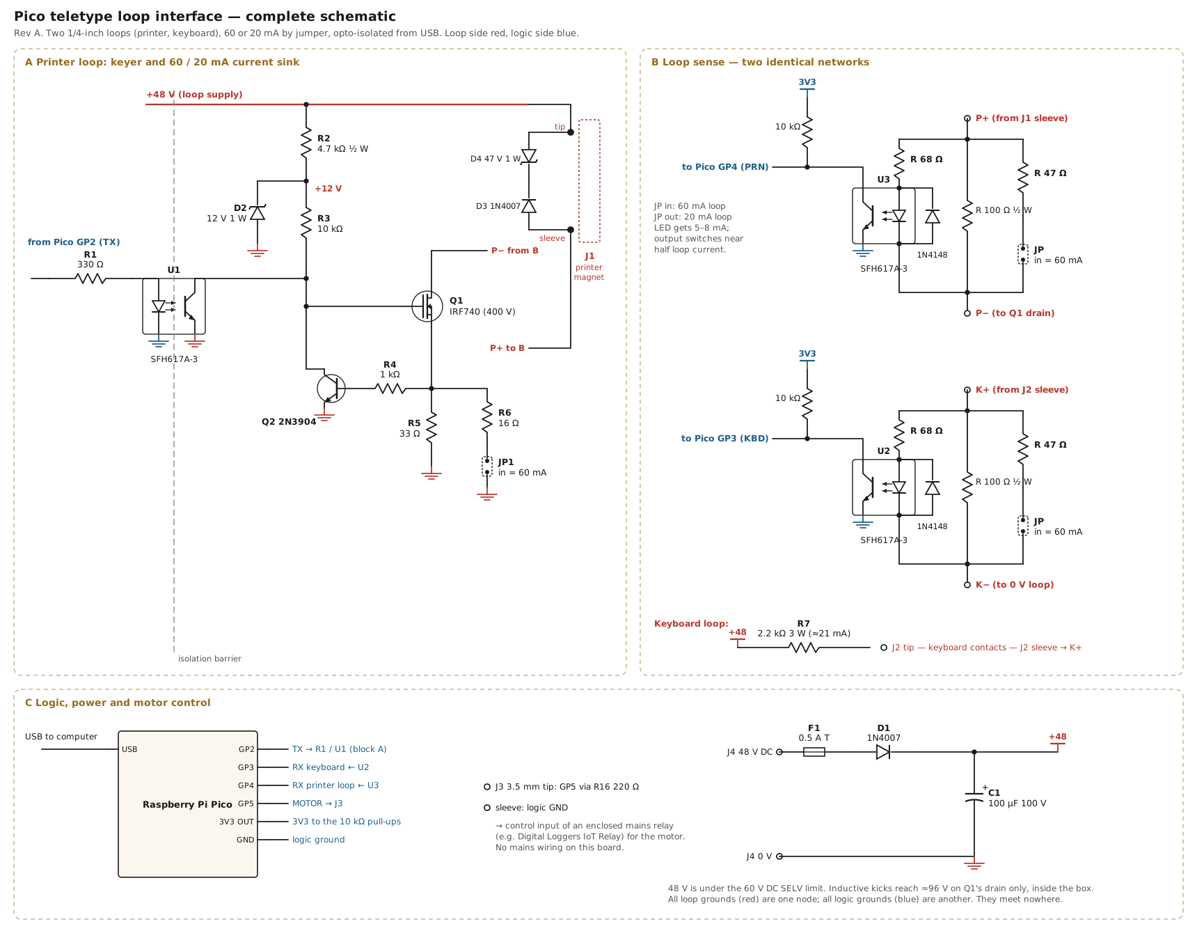
Design B instead of block A. The asymmetric half-bridge of Vol 2 replaces block A outright: GP2 drives its optocouplers (with the opposite sense, high for mark), the keyboard loop runs from its 12 V input, and blocks B and C are unchanged. The firmware’s ~~txinv off command flips the output polarity to suit (Vol 7).
Two loops, not one. The printer (J1) and the keyboard (J2) are on separate loops: full duplex. The computer prints on the machine through J1 and reads the keyboard through J2, and if the typist wants to see what they type, the firmware echoes it to the printer. Most modern interfaces want it this way; the DeRamp board requires it. A machine that cannot be rewired can stay half duplex: keyboard and magnet in series on J1, and the printer-loop sense network (U3) reads everything on the loop, including the computer’s own sending, which the firmware then has to ignore.
The keyboard loop supply. The keyboard contacts need current, but not the magnet’s fast edges, so J2 is fed from the 48 V rail through R7, 2.2 kΩ, about 21 mA. That resistor dissipates about a watt while the keyboard idles at mark, which is why it is a 3 W part mounted clear of the board.
Motor control. The Pico’s GP5 drives a 3.5 mm jack intended for the control input of an enclosed, listed mains relay, such as the Digital Loggers IoT Relay II, whose input works from 3 to 48 V DC and draws a few milliamperes. RevK’s ASR-33 board switches its motor through a solid-state relay for the same reason: turning the motor off between messages saves wear, noise and power. Keeping the mains switching in a closed commercial product keeps mains wiring off the interface board.
3.6 Route 1: USB-serial chips
If a USB-serial adapter can produce five data bits at 45 baud, the computer can do the rest in software and the front end above is all the hardware needed. Whether it can depends on the chip, and the chip’s Linux driver is the most direct evidence.
Table 2 — Route 1: USB-serial chips
| Chip | Five data bits? | Can it reach 45.45 baud? | Evidence |
|---|---|---|---|
| FTDI FT232R, FT232B, FT-X | No. “All FTDI UART chips are limited to CS7/8.” | No. The divisor field is 14 bits on a 3 MHz base: 3,000,000 ÷ 16,383 ≈ 183 baud is the floor. | Linux ftdi_sio.c |
| WCH CH340 / CH341 | Yes, 5 to 8 bits; 1 or 2 stop bits | Nearly. Linux clamps to its minimum, 46 bit/s; the nearest divisor gives about 45.8 baud, 0.7 per cent fast and well inside a teletype’s tolerance. The datasheet lists 50 baud natively. | Linux ch341.c; WCH datasheet |
| Silicon Labs CP2102 | Yes, 5 to 8 bits | Not by default (the Linux driver’s floor is 300 baud), but the CP2102’s baud-rate table can be reprogrammed with Silicon Labs’ utility, AN205; John Nagle’s notes map the unused 600 baud entry to 45 baud. Some adapters are locked at the factory. | Linux cp210x.c; aetherltd.com |
| 16550 UART (a real PC serial port) | Yes, and with five data bits and “2 stop bits” selected it sends 1.5 | Yes: divisor 2535 on the 1.8432 MHz clock gives 45.44 baud | 16550 behaviour; Linux-kernel list, 2007 |
The table explains a piece of folklore. BaudotRSS’s documentation warns that “USB to serial converters will usually not work at 45.45 baud” and that “some USB to serial devices must be configured to run at a false baud rate. For the device we use, the baud rate in the configuration file is set to 600 baud … and the device runs at 45.45 baud.” That device is the reprogrammed CP2102, and HeavyMetal’s author added 600-baud support “for Nagle’s USB-RS232 adapter” for the same reason. FTDI adapters, the most common kind, cannot do it at all.
European machines have an easier time. A German telex machine on a TW39 line runs at 50 baud, which a CH340 does natively; the piTelex project connects TW39 machines to a Raspberry Pi or a USB-serial adapter with an analog 40 mA current regulator and a switching transistor, and its software reads “50 baud, 5 data-bits”.
3.7 The ASCII machines
The Model 33 and Model 35 are a different, easier case, and Vol 4 covers their character format. Electrically, three things differ.
- 20 mA, and no large magnet in the loop. The Model 33’s selector magnet is driven by a transistor inside the machine (Vol 1). The loop sees an input that is “essentially resistive”, and short local loops were specified at 16 to 22 volts.
- Both loops are passive. RevK’s description of his ASR-33 controller puts it plainly: “the ASR33 is passive for SEND and RECEIVE”, so the interface must supply the current for both. His board uses two NCR402U constant-current LED drivers, one per loop, set to 20 mA; a FET switches the receive loop and an optocoupler senses the send loop.
- The machine can power the interface. Mike Douglas’s DeRamp TTY adapter for the Model 33 plugs in inside the machine and “obtains power and access to the Teletype data loops” from it, presenting an RS-232 port on an RJ-14 jack. It is sold assembled for $49. The Altair-clone site’s RS-232 interface for the ASR-33 is a similar circuit, “very similar to the current-loop interface used by MITS on their serial I/O boards”, powered from a 12 V adapter plugged into the 33’s own convenience outlet.
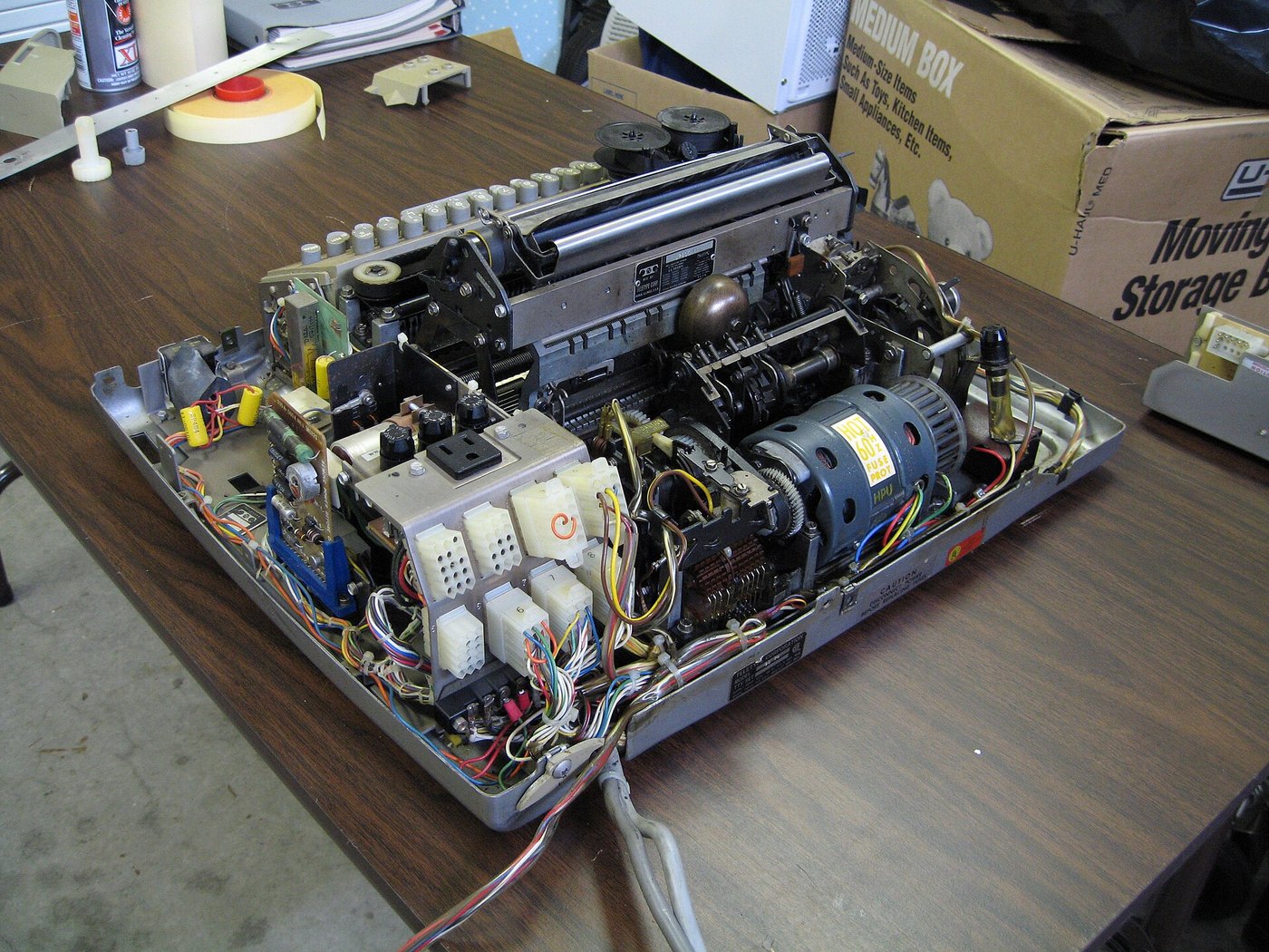
The Pico interface drives a Model 33 with JP1 out (20 mA) and the firmware’s ASCII mode (Vol 7). Its 48 V supply is more than a 33 needs, and the current sink simply absorbs the difference.
3.8 What exists today
The field is small, specialised and mostly the work of individuals. Everything in this table was checked on 3 November 2026.
Table 3 — What exists today
| Interface | What it is | Loop side | Host side | Status |
|---|---|---|---|---|
| DeRamp Model 15 interface (Mike Douglas) | ASCII⇄Baudot or Baudot pass-through, speed conversion, AFSK demodulator, regenerative loop drive from a 15 V adapter (Vol 2) | 60 mA neutral, full duplex; 60/67/75/100 wpm; US-TTY or ITA2 | RS-232 9600 8N1, RJ-14 | bare board and programmed PIC, $20; assembly per the manual |
| DeRamp TTY adapter for the Model 33 | plug-in RS-232 adapter powered by the 33 | the 33’s 20 mA loops | RS-232 on RJ-14 | assembled, $49 |
| W6IWI DSP terminal unit (Harold Hallikainen) | DSP RTTY TU with AFSK generator, loop keying and sensing | 60 mA | USB, audio | KiCad files on GitHub; bare or assembled boards via PCBWay |
| epvuc usb-tty | USB CDC firmware for ATmega32U2/32U4 loop adapter boards; translating or transparent mode; ASCII mode | needs an external loop supply | USB | firmware on GitHub |
| piTelex (FabLab Würzburg) | Python telex software for a Raspberry Pi or PC, with a TW39 adapter | 40 mA current regulator + transistor, 50 baud | GPIO or USB-serial | GPL-3.0, GitHub |
| i-Telex | a telex network over the internet, with plug-in interface cards | TW39 and ED1000 | internet | community network, mostly in Germany |
| Telebyte TB65A | commercial RS-232 to 20/60 mA current-loop converter with its own supply | 20 or 60 mA | RS-232 | sold by L-com; a general-purpose converter, not a teletype interface (no Baudot, no 45 baud) |
| ttyloopdriver (John Nagle) | USB-powered 60 mA driver: boost-charged dump capacitors, 15 V sustain (Vol 2) | 60 mA | USB (CP2102) | open-source design on GitHub, GPL-3.0; the Animats kit version is discontinued |
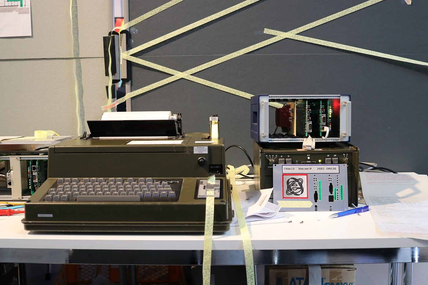
Two observations from the table. First, every serious interface is full duplex and opto-isolated, and most keep the high voltage either inside a purpose-built board or out of the design altogether. Second, the hard part is never the electronics. It is the timing and the code, the subject of Vol 4.
Next: Vol 4, the software side — Baudot, LTRS and FIGS, odd baud rates and the tools that drive a teletype from a computer.
3.8.1 Sources (Vol 3)
- H11AA1 in a 60 mA loop, transition near 27 mA; contact bounce with a Model 14 TD; biquad low-pass at 0.5 × baud rate; KiCad on GitHub; boards via PCBWay. Harold Hallikainen W6IWI, “DSP TU Part 3.” https://w6iwi.org/rtty/DspTU3/ ; PCBWay project page https://www.pcbway.com/project/shareproject/DSP_Terminal_Unit_for_RTTY_f7e5daa3.html
- Half-current switching in Teletype receivers: Sections 570-224-100 (TP177010) and 574-123-101 (Model 33 call control unit); see Vol 1 sources.
- Nagle’s interface board: HSR-312L optocoupler/solid-state relays, Omron G3VM-401B replacement, opto-isolators facing opposite directions to separate the high- and low-voltage sections, 120 V DC loop, 2 kΩ 10 W resistor. https://www.aetherltd.animats.com/connecting.html
- CP2102 reprogramming (Silicon Labs AN205 utility; remap 600 baud to 45; some devices locked). https://www.aetherltd.animats.com/connectingusb.html
- BaudotRSS on USB adapters and the 600-baud “false baud rate”; RTS motor relay. John Nagle, BaudotRSS README. https://github.com/John-Nagle/baudotrss
- HeavyMetal 600-baud support “for Nagle’s USB-RS232 adapter”; DTR/RTS control. Javier Albinarrate LU8AJA, HeavyMetal page. https://www.albinarrate.com/index.php?option=com_content&view=article&id=51:heavymetal
- Linux USB-serial drivers (read 2026-11-03 from torvalds/linux master):
drivers/usb/serial/ftdi_sio.c(“All FTDI UART chips are limited to CS7/8”; 232BM divisor = base ÷ baud with a 14-bit integer field on a 3 MHz base);drivers/usb/serial/ch341.c(CH341_MIN_BPS= 46; CS5 supported; 1 or 2 stop bits);drivers/usb/serial/cp210x.c(CS5 supported; minimum speed 300). https://github.com/torvalds/linux/tree/master/drivers/usb/serial - CH340 datasheet: 50 bps to 2 Mbps; 5, 6, 7 or 8 data bits; 1 or 2 stop bits. WCH, CH340 datasheet (SparkFun copy). https://cdn.sparkfun.com/datasheets/Dev/Arduino/Other/CH340DS1.PDF
- 16550 divisor 2535 → 45.44 baud on a 115,200 base (“a 0.01% error rate”). Stuart MacDonald, reply to w1hkj, “Serial port blues,” linux-kernel list, January 2007. https://lkml.iu.edu/hypermail/linux/kernel/0701.2/1084.html
- piTelex: TW39 adapter with an analog 40 mA current regulator and switching transistor; 50 baud, 5 data bits; GPL-3.0. https://github.com/fablab-wue/piTelex
- i-Telex: TW39 and ED1000 compatible; plug-in system cards. https://www.i-telex.net/
- RevK ASR-33 controller: ASR33 passive on SEND and RECEIVE; two NCR402U constant-current sources; FET transmit; optocoupler receive; solid-state relays for power and motor. Adrian Kennard, “The new ASR33 controller board,” 7 February 2022. https://www.revk.uk/2022/02/the-new-asr33-controller-board.html
- DeRamp TTY adapter for the Model 33 ($49, powered by the Teletype, RJ-14). https://deramp.com/tty_adapter.html · DeRamp Model 15 interface ($20 board + PIC). https://deramp.com/model15_interface.html
- Altair-clone ASR-33 RS-232 interface (12 V adapter in the 33’s outlet; MITS-like circuit). https://altairclone.com/teletype.html
- epvuc usb-tty firmware (ATmega32U2/16U2/32U4, LUFA, translating and transparent modes, ASCII mode). https://github.com/epvuc/usb-tty
- Telebyte TB65A RS-232 to current-loop converter. L-com product page. https://www.l-com.com/serial-converters-controller-cards-telebyte-rs232-to-current-loop-converter-includes-power-supply
- Animats TTYLoopDriver kit — discontinued. https://animats.com/classic/topics/products.html ; open design: https://github.com/John-Nagle/ttyloopdriver
- Digital Loggers IoT Relay II: control input 3–48 V DC, ≈2–3 mA. https://www.digital-loggers.com/iot2faqs.html ; spec sheet https://www.digital-loggers.com/iot2Spec.pdf
- SFH617A CTR and isolation rating: Vishay datasheet.
- Cross-links: Restoring a Teletype, Vol 2; Making the Parts That No Longer Exist, Vol 2; The Teletype Model 15, Vol 6 (which also lists the Volpe board and CuriousMarc’s Arduino interface).