Interfacing Teletypes and Paper Tape · Volume 6
Interfacing Teletypes and Paper Tape — Vol 6: Paper Tape In and Out of the Computer
The tape as a data format, chadded and chadless, punching tape from a computer, reading it back through a transmitter-distributor or an optical reader, eyeball banners and Baudot art, and archiving old tapes by scanning them.
6.1 The tape is a file
The pink tape that spooled onto the floor of my father’s shack was, in modern terms, a file. It was a sequence of bytes, five bits wide, written by one machine and readable by any other, and it outlived the moment that made it. Paper Tape and the Perforator tells its history and how to read it by eye. This volume treats it the way a computer does: as a storage medium with a precise physical format, which can be written from a program, read back into one, and rescued, decades later, by a scanner.
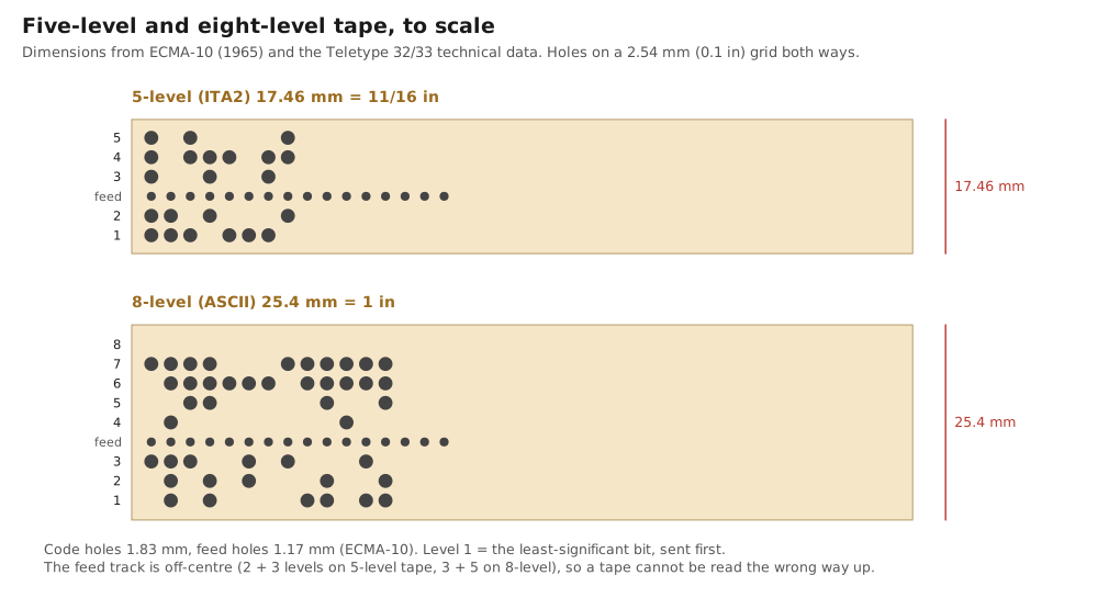
The geometry is standardised, and the standard is short. ECMA-10, first published in November 1965, specifies:
Table 1 — The geometry is standardised, and the standard is short. ECMA-10, first published in November 1965, specifies
| Dimension | Value |
|---|---|
| Tape width, 8-level | 25.40 mm (1 in), ±0.05 mm |
| Tape width, 5-level | 17.46 mm (11/16 in) |
| Thickness | 0.100 mm |
| Code hole diameter | 1.83 mm |
| Feed hole diameter | 1.17 mm |
| Pitch, along and across | 2.54 mm (0.1 in) |
| Feed track (8-level) | between tracks 3 and 4, 9.96 mm from the reference edge |
Teletype’s own technical data for the Model 33’s punch agree: 5- or 8-level tape, 11/16 inch or 1 inch wide, “code combinations per inch … 10”, feed hole diameter 0.0465 inch. Three properties of the format matter to software.
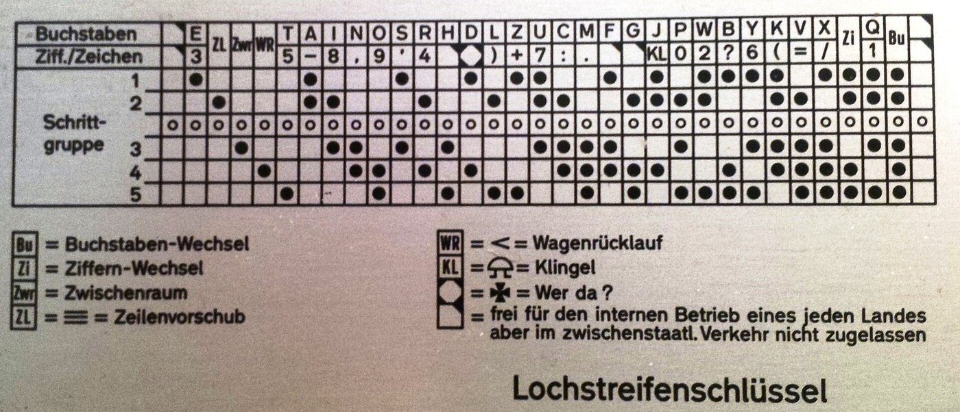
- The feed track is off-centre. On 8-level tape there are three tracks on one side of it and five on the other; on 5-level tape, two and three. A tape cannot be read upside down by accident, and a program reading an image of one can work out which way up it is (below). Track numbering is a convention, not a law: Teletype and the US Navy numbered 5-level tape 1 2, feed, 3 4 5 (the chart in Vol 4), while other sources count from the other edge and say the feed track is “between 3 and 4”. It is the same tape.
- Every row has a feed hole. The feed holes are punched whether or not any code holes are, so a stretch of tape with feed holes and nothing else is blank tape, the leader and trailer that let a tape be threaded and held.
- All holes means “nothing”. A punch cannot un-punch a hole, so the code with every hole punched was reserved as a non-character that the reader ignores. On 5-level tape it is LTRS (
11111); on 8-level tape it is DEL, ASCII 127, whose position at the end of the ASCII table was chosen for exactly this reason. An operator who punched a wrong character backed the tape up one row and over-punched it with all holes: a rubout.
6.2 Chadded and chadless
When a punch pin goes through tape, it removes a small disc of paper: chad. Ordinary tape is fully punched, or chadded, and the chad falls into a box under the punch (the Model 33 has a “metallic chad container which collects the paper (chad) punched out by punch pins”).
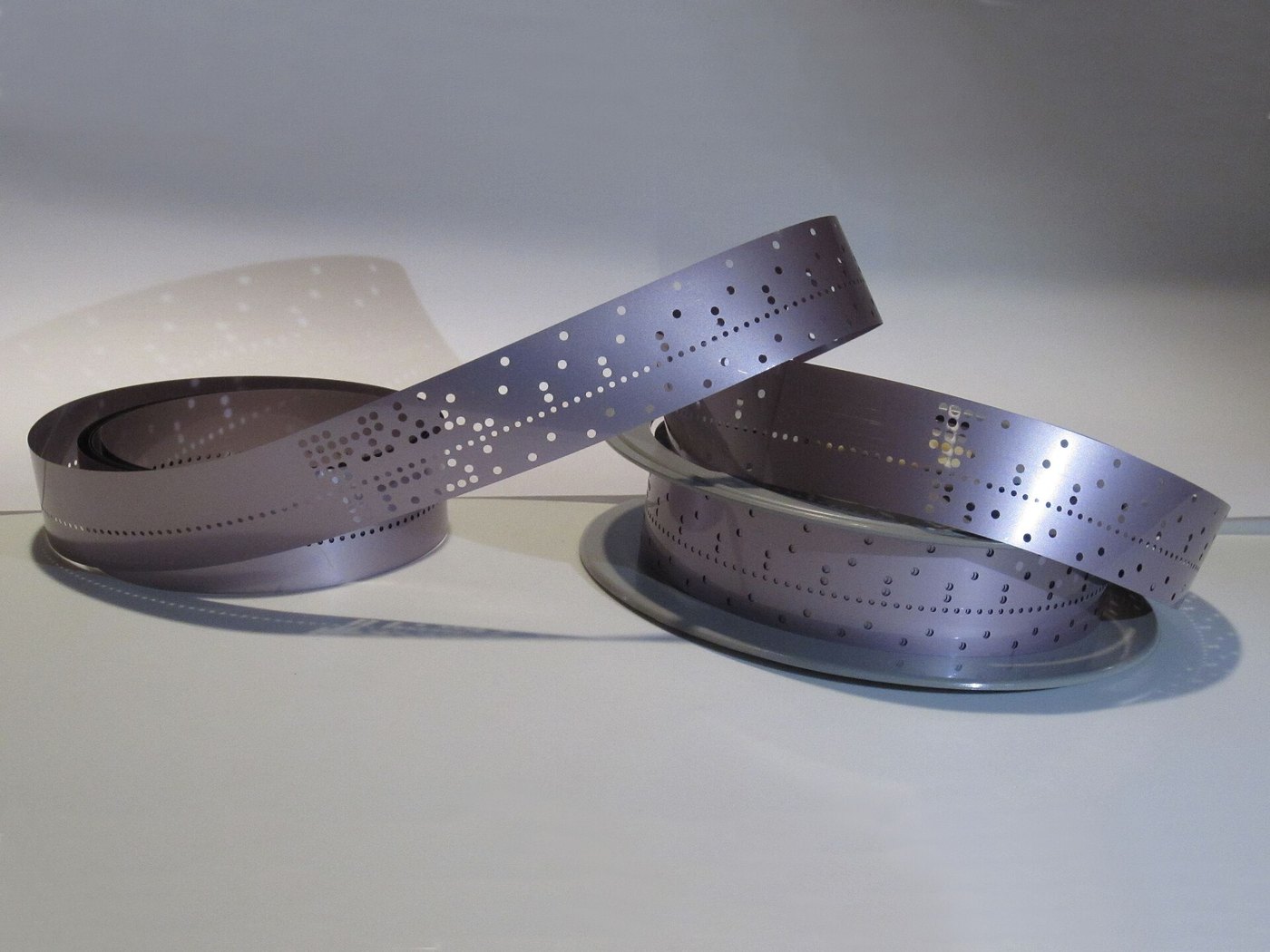
Chadless tape is punched so that each disc stays attached by a small hinge of paper, folded back out of the way. Chadless tape has two advantages. There is no chad to sweep up, and, more importantly, characters can be printed on the tape over the holes, because the paper is still there. That is what a typing reperforator does: it punches the received signal and types each character along the tape, so an operator in a torn-tape relay office could read the message without decoding the holes.

The flaps that make chadless tape readable by people can make it harder to read by light. A mechanical reader’s pins push a flap aside, but an optical reader looking through the tape sees a hole that is only partly open. An optical reader for old chadless tape should have a sensitive threshold, and the calibration step in Vol 7’s reader exists partly for this reason.
6.3 Punching tape from a computer
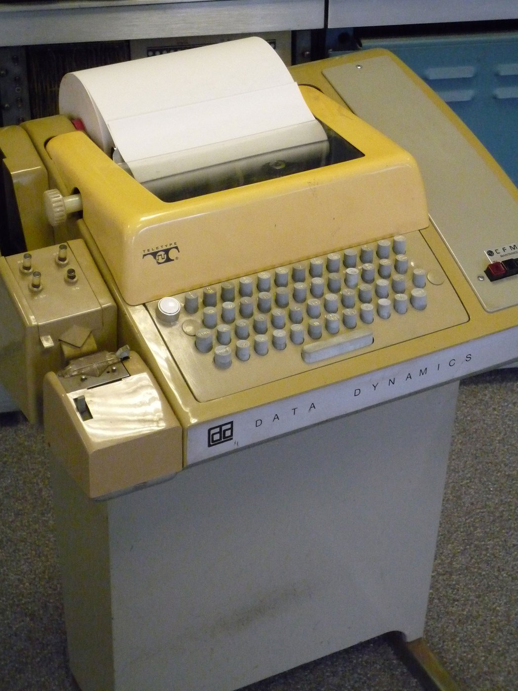
An ASCII machine. A Model 33 ASR punches whatever passes through it whenever its punch is switched on, by the ON button beside the punch or, on suitably equipped machines, by the control codes of Vol 4: DC2 (“TAPE”, on the R key) to start the punch and DC4 to stop it. A program punches a tape by sending, in order:
- DC2, to switch the punch on (or ask the operator to press ON);
- a leader of about 30 cm of blank tape: NUL characters, which punch feed holes only;
- the data, at ten characters a second;
- a trailer of NULs, and DC4.
The Model 33 punches all eight levels, so a program can punch binary, not just text, provided the interface passes every byte through untouched. The Pico interface’s ~~raw on mode does exactly that (Vol 7), which is also how it would punch a program tape for a 1970s minicomputer.
A Baudot machine. A five-level reperforator, such as a Model 14 typing reperforator or a Model 28 LPR, is a punch with its own selector magnet. Electrically it is just another receiving machine, and it hangs on a loop exactly like a page printer; the interfaces of Vols 2 and 3 drive it without change. The Teletype Model 15, Vol 7, describes the Model 14 family, and The Teletype Model 28 covers the LPR and LRXB. To punch arbitrary five-bit codes rather than translated text, the interface must pass codes through raw, as the DeRamp board’s Baudot pass-through mode and the Pico firmware’s raw mode both do.
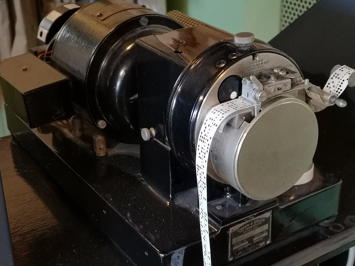
High-speed punches. Computer rooms used dedicated punches that run at tens of characters per second, Teletype’s BRPE and the Facit and GN Telematic units among them. The GNT 4601 and 4604 punch-and-reader stations were common in CNC machine shops, and the Santec GNT-4606 succeeded them. They turn up second-hand, mostly with RS-232 interfaces, and they are the practical answer to punching a long tape quickly; a teletype punch at ten characters a second takes a minute and forty seconds per thousand bytes.
6.4 Reading tape into a computer
Through the machine’s own reader. A teletype’s tape reader is called a transmitter-distributor (TD), and it is the twin of the keyboard. It senses each row of holes with pins and sends the character on the loop as start-stop signals, through contacts that open and close the loop exactly as keyboard contacts do. A loop interface reads a TD exactly as it reads a keyboard. The only extra requirement is control: the computer must be able to start and stop the reader. The Model 33’s reader is started and stopped by a trip magnet, “automatic reader control” on machines equipped with a relay and a 32 V rectifier for it, so that the received codes X-ON and X-OFF start and stop the tape. That is the origin of the XON/XOFF flow control that every serial terminal still understands. Five-level TDs, such as the Model 14 TD and the Model 28 LXD, have their own start magnets or clutch controls (see the Model 15 and Model 28 dives).
A TD reads at the line’s speed: about six characters a second at 60 wpm. That is fine for a message and hopeless for an archive.
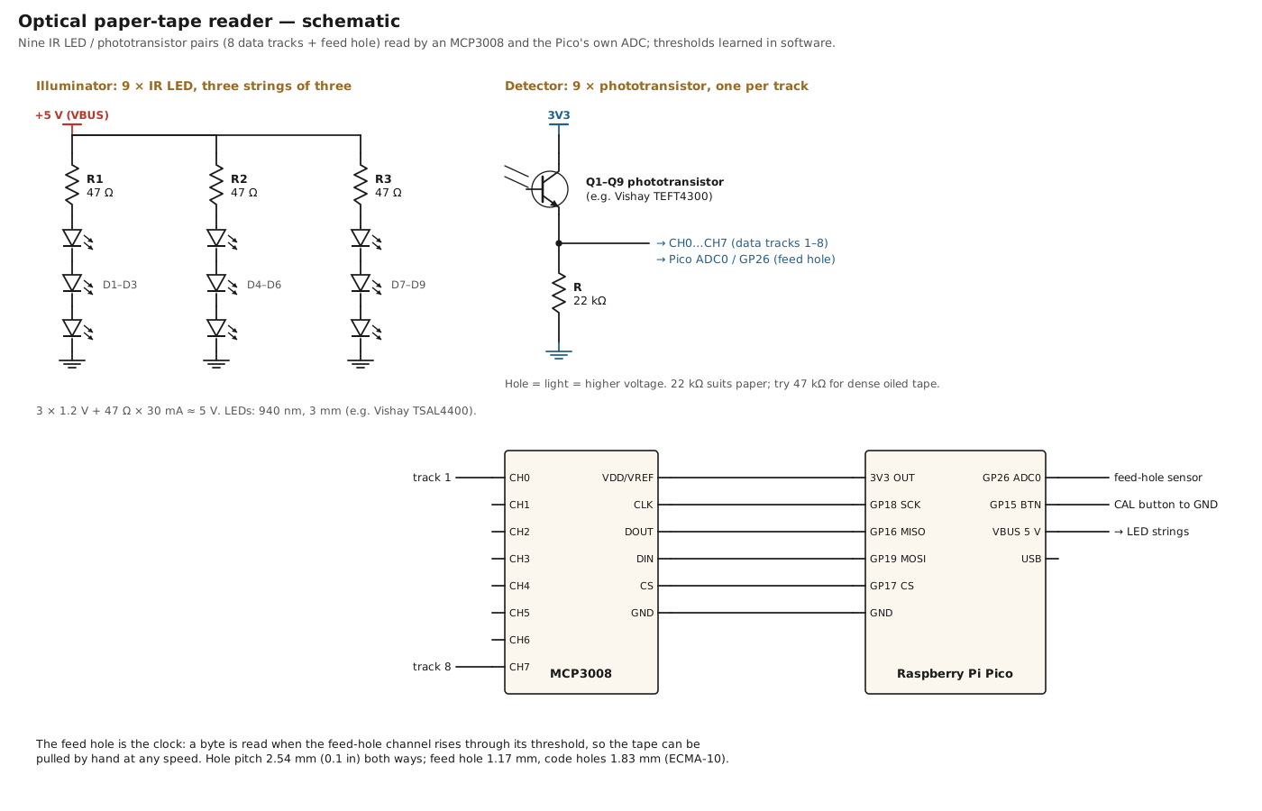
Optical readers. A photoelectric reader shines light through the tape onto a row of sensors, one per track plus one for the feed holes, and reads a row whenever a feed hole passes. Because the feed hole is the clock, the tape can move at any speed, including by hand. Commercial readers ran at hundreds of characters a second; a hobby reader can be built in an afternoon.
The best documented modern design is Jürgen Müller’s e-basteln paper tape reader: LED and phototransistor pairs for eight data tracks and the feed track, read by the analog inputs of a SparkFun Pro Micro (ATmega32U4), with the thresholds set in software by a calibration run of “about 30 cm of test tape”, stored in EEPROM. It reads 5- to 8-level tape, appears to the computer as a USB serial port, and is fast: “reading at 1.2 meter/second (500 characters per second) should not be a problem”, and it works handheld “at up to 1 meter/second”. The design files, Arduino code, bill of materials and even a spreadsheet for drawing tapes are on its building page. Hackaday covered it in April 2022 as “Paper Tape Reader Self-calibrates, Speaks USB”.
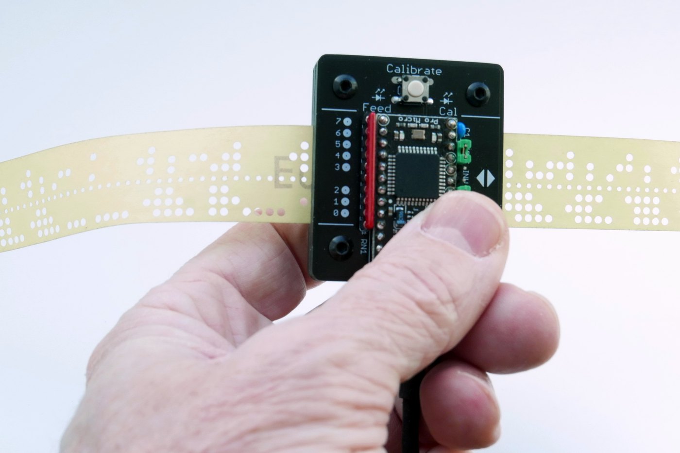
This dive’s reader (Vol 7) follows the same principles with a Raspberry Pi Pico: nine IR LED and phototransistor pairs, an MCP3008 for the eight data tracks, the Pico’s own ADC for the feed track, a calibration button, and peak detection while the feed hole is in view.
6.5 Banners and art
A paper tape can carry a picture as easily as a message, and generations of operators and programmers used that.
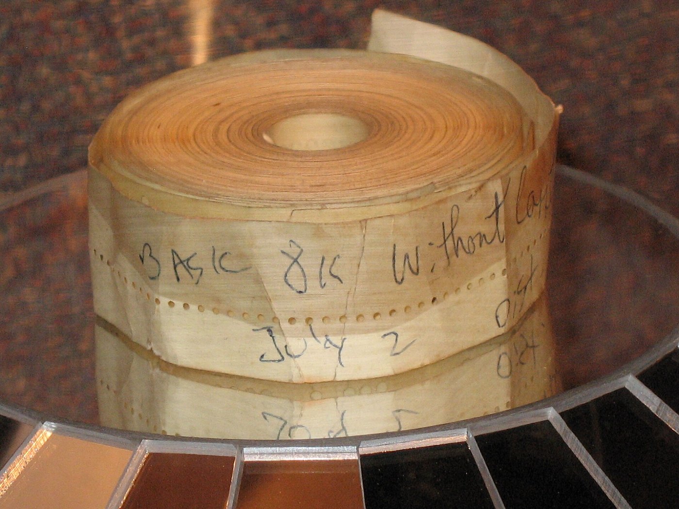
Eyeball characters. Punch the holes in the shape of letters, a column at a time, and the tape carries a human-readable label: “BASIC 8K”, or a name, or a message. HeavyMetal added “eyeball labels in punched tape” in its version 3.0. Hugh Pyle’s ASR-33 tools include printing words on paper tape, and Adrian Kennard’s ASR-33 controller punches “large text on paper tape”. Mark Blair, NF6X, published a GPL-licensed suite, papertape, for drawing realistic images of punched tape, inspired by the BSD Unix bcd game, which prints a card image of its input.
The tape.py tool in this dive does both halves: tape.py banner "TEXT" produces punch data, one byte per tape row, from a 5×7 dot-matrix font, and tape.py svg draws any punch file. Sent to a Model 33 through the raw mode, the banner data punches a label that can be read across the room.


Teletype art. The other tradition is page art: pictures typed on the printer. RTTY.COM’s gallery holds 155 files of “Baudot character art” from the 1960s to the 1980s, using only the letters, digits and punctuation of the five-unit code. The technique is overstrike: “a carriage return without a line feed produces overstrike”, so a line can be typed two or three times to build up darker tones. These pictures were exchanged on the air and on tape, and the files are simply sequences of Baudot codes. Through a raw pass-through interface, a machine can print them exactly as they were printed fifty years ago.
6.6 Archiving old tapes
Old tapes are worth rescuing. Program tapes for early computers, logged messages, a station’s own tapes: many survive only as paper, and paper tape decays. Oiled tape goes gummy, ordinary paper tape becomes brittle and tears at the feed holes, and Mylar tape, made for programs that had to be read hundreds of times, survives best.
There are three ways to read an old tape, in order of gentleness.
- A hand-pulled optical reader (Vol 7, or the e-basteln design). The tape slides over a smooth surface with no sprockets and no tension, and the feed hole clocks each row.
- A powered reader of the period, if the tape is strong enough for its sprocket wheel.
- A scanner. For a tape too fragile to pull, lay it flat on a flatbed scanner, face down, with a dark cover over it so that the holes show dark against the light paper, and scan at 300 dpi or more. A long tape is scanned in overlapping segments.
tape.py decode reads such an image. It thresholds the image (Otsu’s method), finds every hole as a connected blob, separates the small feed holes from the larger code holes by area (the ratio is (1.17/1.83)², about 0.41), fits a line through the feed holes to find the tape’s angle, measures the feed-hole spacing to find the scale, and then assigns each code hole to a row and a track. It decides which way up the tape is by trying both orientations and keeping the one in which the holes fall on the off-centre track pattern, and it reverses the row order if the tape was scanned end for end. Its self-test renders synthetic tapes, rotates them, adds noise, turns one upside down, and checks that both a five-level Baudot message and an eight-level ASCII string come back exactly. It has not yet been tried on a real scan; the first real archiving job will test it properly.
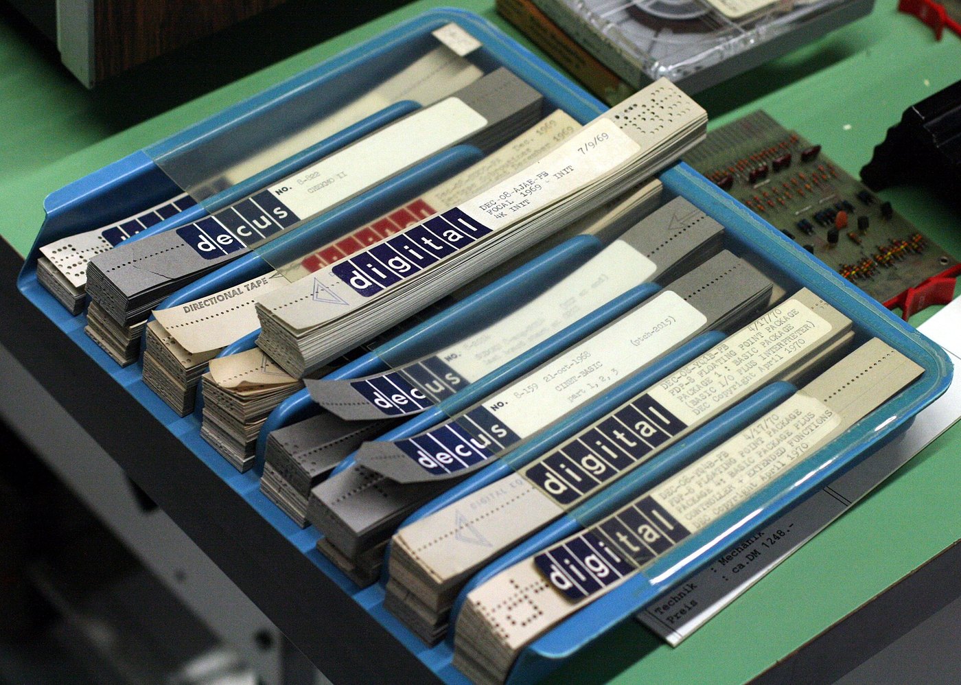
A good archive keeps three things for every tape: the images, the decoded bytes, and a note of where the tape came from, what its label says and how it was read. The images are the primary record, because a better decoder can always be written later, and the tape itself may not survive another reading.
Next: Vol 7, two builds — the Pico loop interface and the optical tape reader.
6.6.1 Sources (Vol 6)
- ECMA-10, Standard for Data Interchange on Punched Tape, 1st edition, November 1965: widths 25.40 mm and 17.46 mm, thickness 0.100 mm, code holes 1.83 mm, feed holes 1.17 mm, pitch 2.54 mm, feed track between tracks 3 and 4, 9.96 mm from the reference edge. https://ecma-international.org/wp-content/uploads/ECMA-10_1st_edition_november_1965.pdf ; transcription at https://polyomino.org.uk/computer/ECMA-10/
- Model 33 tape punch and reader data (5- or 8-level, 11/16 in or 1 in, 10 combinations per inch, feed hole 0.0465 in; chad container; ON/OFF/REL/B.SP. pushbuttons; automatic reader control with a 32 ± 8 V relay rectifier; XON “tape reader on”). Teletype Bulletin 273B Vol 1 (1964), Section 574-100-102; 32 and 33 Tape Punch — Principles of Operation, Section 574-125-100TC. https://navy-radio.com/manuals/tty/jh/bsps/bsp/570series/574-125-100TC.pdf
- DEL as the tape-erasure character: ASCII’s all-ones code 127 (Wikipedia, “Delete character,” https://en.wikipedia.org/wiki/Delete_character); five-level over-punching with LTRS: Paper Tape and the Perforator.
- DC2/DC4 punch control and the “R TAPE” keytop: see Vol 4 sources ⟨the DC4 legend is unconfirmed by photograph⟩.
- GN Telematic 4601/4604 and Santec GNT-4606: Centre for Computing History, https://www.computinghistory.org.uk/det/41928/GN-Telematic-4601-Tape-Reader-Punch-Station ; Crypto Museum, https://www.cryptomuseum.com/telex/santec/gnt4606/index.htm
- e-basteln paper tape reader (Jürgen Müller): LED/phototransistor pairs, Pro Micro (ATmega32U4), software thresholds from ~30 cm of calibration tape in EEPROM, 5- to 8-level, 500 characters per second, handheld to 1 m/s, design files and BOM. https://e-basteln.de/computing/papertape/overview/ ; https://e-basteln.de/computing/papertape/building/ ; Hackaday, “Paper Tape Reader Self-calibrates, Speaks USB,” April 2022.
- HeavyMetal eyeball labels (v3.0): https://www.albinarrate.com/index.php?option=com_content&view=article&id=51:heavymetal · Hugh Pyle, ASR33 (paper-tape words): https://github.com/hughpyle/ASR33 · RevK (“punching large text on paper tape”): https://www.revk.uk/2022/02/the-new-asr33-controller-board.html · NF6X papertape (GPLv3; inspired by BSD
bcd): https://www.nf6x.net/?p=6642 ; https://gitlab.com/NF6X_Retrocomputing/papertape - RTTY.COM art gallery: 155 Baudot character-art files, overstrike. https://rtty.internet-tty.net/gallery.html
- The Model 14, 19 and 28 tape machines: The Teletype Model 15, Vol 7 (https://dots-and-dashes.fubsypoly.com/teletype-model-15/) and The Teletype Model 28 (https://dots-and-dashes.fubsypoly.com/teletype-model-28/).
- Code:
03-outputs/tools/tape.py(banner, svg, decode; self-test),03-outputs/firmware/tape_reader/main.py.