The Shift-Keying Family · Volume 2
The Shift-Keying Family — Vol 2: Phase, Constellations, and the Tail-Eating Mode
PSK31 borrowed Morse's oldest idea — short codes for common letters — and made it a bit stream. Then quadrature turned two carriers into one, and GMSK closed the loop by being an FSK and a PSK simultaneously.
2.1 The third knob
Amplitude is fragile. Frequency is robust and costs bandwidth. Phase is the subtle one, and it is where nearly all modern digital communication lives — your phone, your Wi-Fi, the satellite feeding your television, and on the HF bands, the mode that made keyboard-to-keyboard chatting fun again.
Phase-shift keying encodes bits by shifting the carrier’s phase between agreed values. The immediate objection is the one from How a Signal Carries Information: phase has no absolute meaning, only a relative one. Shifted relative to what?
You could transmit a separate reference. Nobody does — it is wasteful, exactly as an AM carrier is wasteful. Instead, almost all practical PSK is differential: the information is in the change from one symbol to the next, not in any absolute phase. Did the phase flip between this symbol and the last, or not? A flip is one bit value, no flip is the other. The receiver needs no absolute reference at all, only a memory of what it saw an instant ago — and it becomes immune to slow drift, since a gradual frequency error shifts everything equally and the differences survive.
The simplest form is binary PSK (BPSK): two states, 180° apart. Because a 180° shift is the same as inverting the waveform, BPSK is sometimes called phase-reversal keying, and on an oscilloscope it is unmistakable — the carrier runs along, then abruptly turns inside out, then continues.
2.2 PSK31, and Morse’s idea in a bit stream
PSK31 is BPSK, and it is the most successful of the “new” amateur digital modes — created by Peter Martinez, G3PLX, and released in 1998. Its design is a small masterpiece of choosing the right numbers.
31.25 baud. It looks absurdly slow next to any modern data rate. It is chosen to be approximately 50 words per minute — a comfortable human typing speed. PSK31 is not trying to move files. It is trying to carry a conversation between two people typing, in real time, and it is sized exactly for that job. (Ward’s article gives the rate as “31,” which is the mode’s name; the actual figure is 31.25 baud, chosen because it divides neatly from common sound-card sample rates.)
Roughly 31 Hz of bandwidth. ⟨correction⟩ Ward writes that PSK31 needs “only 50 Hz.” The usual quoted occupied bandwidth is about 31 Hz, and the ARRL’s own PSK31 specification states approximately 60 Hz at −26 dB — a stricter measurement, taken further down the skirts. Fifty is a number lying between the two that matches neither. The reason the figure matters is the reason the mode succeeded: at 31 Hz you can fit dozens of PSK31 conversations into the 2.8 kHz that one SSB voice contact occupies, and on a crowded waterfall you can see them, a picket fence of narrow vertical lines.
A few watts is enough. Concentrating your power into 31 Hz rather than 2,800 Hz is a colossal advantage in signal-to-noise ratio, and PSK31 crosses oceans on 5 watts when the band is open.
2.2.1 Varicode: the direct descendant of Morse
PSK31 does not send ASCII or Baudot. It sends Varicode — variable-length code — and it is the reason this mode belongs in this project and not just any radio book.
Morse code’s central design insight, from 1840, is that the most common letters get the shortest codes. E is one dit. T is one dah. Q and Z, which you hardly ever need, are four elements each. Alfred Vail is said to have counted type in a printer’s case to get the letter frequencies right — a story this project has already flagged as folklore in The History of Morse Code, but the principle is unquestionably there in the code.
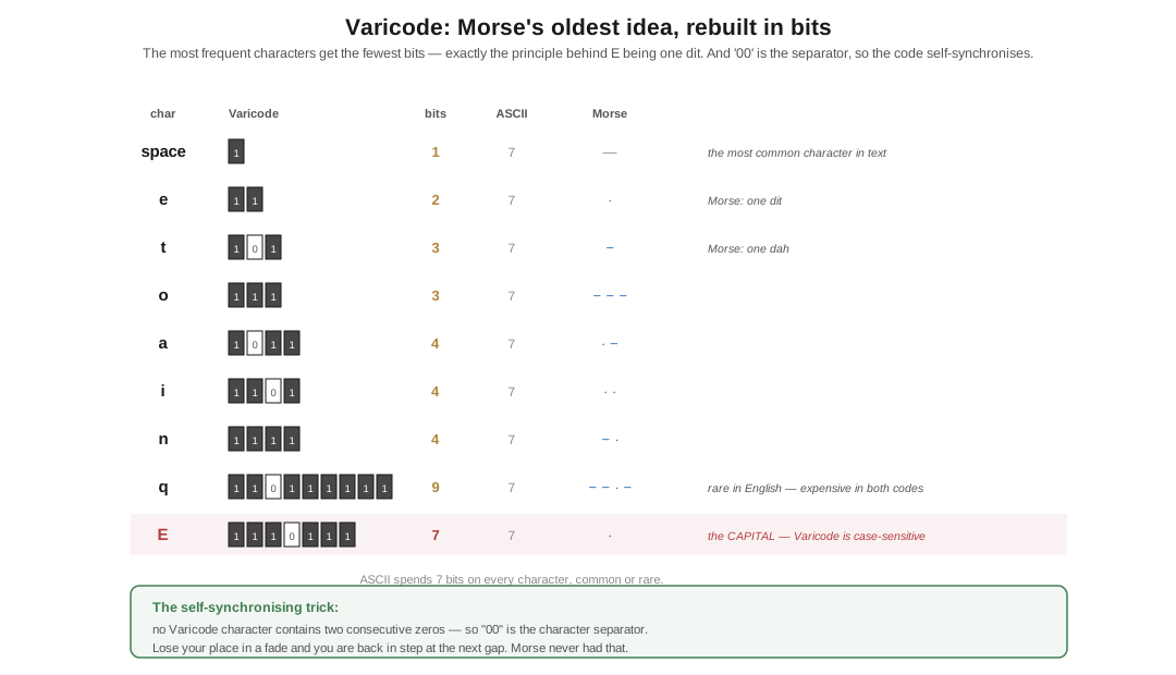
Varicode does exactly the same thing in bits. Common characters get short bit patterns; rare ones get long ones. And because it needs a way to tell where one character ends and the next begins without a start bit, it uses a beautiful trick: no Varicode character contains two consecutive zeros, so two zeros are the separator. The code is self-synchronising. Lose your place in a fade and you are back in step at the next gap.
⟨correction⟩ Ward’s article says “E is one dit in Morse and 1110111 in Varicode.” That is true of capital E — and it undercuts the very point he is making, because seven bits is a long code. The letter you actually type constantly is lowercase e, which is 11. Two bits. Varicode is case-sensitive, and it is optimised for lowercase, because ordinary English text is overwhelmingly lowercase. Capitals are deliberately expensive.
Table 1 — Varicode: the direct descendant of Morse
| Character | Varicode | Bits | For comparison |
|---|---|---|---|
| space | 1 | 1 | the single most common character in text |
e | 11 | 2 | Morse: one dit |
t | 101 | 3 | Morse: one dah |
o | 111 | 3 | |
a | 1011 | 4 | |
E | 1110111 | 7 | Ward’s example — the capital |
So the honest version of Ward’s sentence is stronger than the one he wrote. Varicode is not merely reminiscent of Morse; it applies the same frequency-weighting principle, with the same effect, a hundred and fifty-eight years later, and then adds a self-synchronising property Morse never had. PSK63 is the same mode at double speed and double bandwidth, for when conditions are good and you type fast.
2.3 Quadrature: two carriers in the space of one
Two phase states is not the limit, any more than two tones was. But you cannot simply keep subdividing the phase circle and hope — you need a way to generate and detect intermediate phases cleanly. The answer is quadrature, and it is one of the genuinely elegant ideas in radio.
Take two carriers of the same frequency, 90° apart in phase. Call one I (in-phase) and the other Q (quadrature). Because they are 90° apart, they are orthogonal — mathematically independent. You can modulate each one separately, add them together into a single signal, transmit that, and at the far end separate them again perfectly. Two independent channels occupying one carrier’s worth of spectrum.
Modulate each of I and Q with a simple 0°/180° reversal and combine them, and the sum can take four distinct phases: 0°, 90°, 180°, 270°. That is QPSK — two bits per symbol, twice the data of BPSK in the same bandwidth.
QPSK and 4-QAM are the same signal. Ward makes this point and he is exactly right, and it is worth stating loudly because the two names suggest different things. If instead of phase-reversing I and Q you amplitude-modulate each with +1 and −1, the output is identical — because multiplying by −1 is a 180° phase shift. “PSK” and “QAM” are not two different technologies. They are two different labels for choosing points in the same I/Q plane, and the moment you accept that, the whole modern modulation zoo collapses into one picture.
2.4 Constellations, and what noise does to them
That picture is the constellation diagram, and once you have it you can read any digital modulation scheme at a glance.
Plot I on the horizontal axis and Q on the vertical. Every symbol the transmitter can send is a point. BPSK has two points on the horizontal axis. QPSK has four, one per quadrant. 16-QAM has a 4×4 grid, four bits per symbol. 256-QAM — which your cable modem uses — has a 16×16 grid, eight bits per symbol.
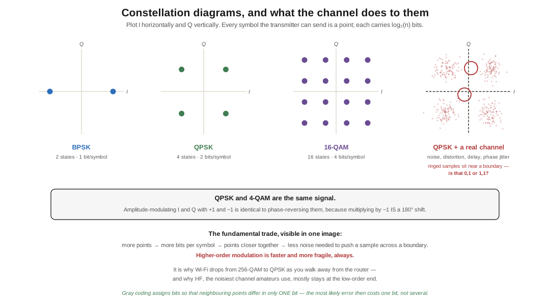
Now the real world. Noise, distortion, multipath delay, phase jitter and amplifier non-linearity all displace each received sample from where it should be. Plot a few thousand of them and the clean points become fuzzy clouds. As long as each cloud stays inside its own decision region the receiver decodes perfectly. When the clouds start to overlap, samples fall on the wrong side of a boundary and you get bit errors — and near a boundary the receiver genuinely cannot tell whether it is looking at a 0,1 or a 1,1.
This makes the fundamental trade visible in a single image. Pack more points in, and each symbol carries more bits — but the points sit closer together, so less noise is needed to push a sample across a boundary. Higher-order modulation is faster and more fragile, always. It is why your Wi-Fi drops from 256-QAM to QPSK as you walk away from the router, and why HF — the noisiest, most abused channel amateurs use — mostly stays down at the low-order end.
2.5 Error control: detect, then correct, then predict
Three escalating answers to the smeared constellation, each historically later than the last.
Detect. A parity bit says whether the number of 1s in a group should be odd or even. If the received group disagrees, something is wrong. You now know you have an error — you cannot fix it, and the protocol must decide whether to ask for a resend (which costs a round trip, and on an HF path with a fade that may be a very long round trip). CRCs are the same idea done properly.
Correct. Forward error correction sends extra bits, computed from the data, chosen so the receiver can not only spot errors but work out what the original must have been — no retransmission needed. FEC costs throughput: you are transmitting bits that are not your message. But over a channel that errors often, the total time to get a clean copy through drops, because you are not spending it on retries. This is the single biggest reason modern weak-signal modes work at all.
Predict. The most sophisticated step is to design the code so that not every sequence of constellation points is legal. If the receiver knows which points can follow which, an ambiguous sample can often be resolved by what came before and after — pick the legal path through the sequence that best fits everything received. Viterbi decoding does exactly this, and its combination with the modulation itself is trellis-coded modulation. Gray coding is the humble, essential companion: arrange the bit assignments so that adjacent constellation points differ in only one bit, and then the most likely error — slipping to a neighbouring point — costs you one bit instead of several.
Hamming, Reed–Solomon, Viterbi, and today LDPC and turbo codes are the names on the milestones. It is worth noticing where this subject comes from: coding theory grew out of the same 1940s Bell Labs work as Shannon’s information theory, and its other parent is cryptography. The people who worked out how to keep a message intact and the people who worked out how to keep it secret were often the same people in the same building.
2.6 GMSK: the family eats its own tail
One last mode, because it is where the neat taxonomy of this dive breaks down in the most satisfying way — and because the seed article gets it wrong.
⟨correction⟩ Ward’s Part 2 states that “the popular VHF/UHF D-STAR system uses 4-PSK.” It does not. D-STAR’s DV mode is GMSK at 4800 bit/s. The published D-STAR specification does permit QPSK and 4-FSK, which is very likely where the error came from — but only GMSK was ever implemented in shipping radios. Every D-STAR handheld on the air is a GMSK radio.
And GMSK is the joke at the end of the family tree. Minimum-shift keying is a form of frequency-shift keying — you can describe it entirely as switching between two frequencies, with the shift chosen to be the minimum that keeps the two orthogonal (exactly half the symbol rate), and with the phase kept continuous across every transition so there are no abrupt jumps to splatter energy into the neighbours. It is FSK, plainly.
It is also, exactly and provably, a form of offset QPSK. The same waveform, described in the I/Q plane, is a quadrature phase-shift-keyed signal whose I and Q transitions are staggered by half a symbol. Not “similar to.” The same signal. Two complete descriptions of one thing.
The G adds a Gaussian filter to the data before modulation, rounding off the transitions to squeeze the spectral skirts down still further. The result is constant-envelope — so it gets FM’s cheap efficient non-linear amplifier from the previous dive — and narrow, and well-behaved. Which is why it is not only in D-STAR but in GSM, and in the Bluetooth link that Ward himself uses as an example on the very first page of Part 1.
So the family that started with a telegraph key closes on a mode that is simultaneously an FSK and a PSK, is used by a billion phones, and is the direct engineering descendant of somebody deciding that E should be one dit. That is the whole sub-project in one paragraph.
2.6.1 Sources (Vol 2)
- H. Ward Silver, N0AX, “Wireless Modes — Part 2,” Nuts & Volts, May 2017 — differential PSK, BPSK as phase-reversal keying, PSK31 and Varicode, quadrature/I-Q, the QPSK≡4-QAM equivalence (correct and well made), constellation diagrams and the effect of noise, and parity → FEC → Gray/Hamming/Viterbi. 🔴 Contains the three corrections addressed above: the D-STAR modulation, the PSK31 bandwidth, and the Varicode
Eexample. https://www.nutsvolts.com/magazine/article/wireless-modes-part-2 - 🔴 Varicode: ARRL, “PSK31 Spec” — space =
1,e=11,t=101,o=111,a=1011,E=1110111; a minimum of two zeros between characters, a pattern that never occurs inside a character. Mode runs at 31.25 baud, ~50 WPM, “approximately 60 Hz at −26 dB.” http://www.arrl.org/psk31-spec · Overview: http://www.arrl.org/psk31-an-introduction-to-narrowband-digital - PSK31 was created by Peter Martinez, G3PLX (released 1998).
- 🔴 D-STAR: DV mode is GMSK at 4800 bit/s; the specification permits GMSK, QPSK and 4-FSK but only GMSK was implemented. Wikipedia “D-STAR” (→ its citations) and the JARL D-STAR specification; see also K0NR, “Investigating the D-STAR Modulation Format.” https://en.wikipedia.org/wiki/D-STAR · https://www.k0nr.com/wordpress/2008/12/investigating-d-star-modulation-format/
- MSK as simultaneously a continuous-phase FSK and an offset-QPSK is a standard result in digital communications texts (Proakis; Xiong, Digital Modulation Techniques). GMSK’s use in GSM and Bluetooth is likewise standard.
- Cross-links: Morse & CW → The History of Morse Code (the letter-frequency principle Varicode inherits, and the type-case folklore); The Shift-Keying Family Vol 1; Weak-Signal Modes & FT8 (where FEC stops being an add-on and becomes the whole design).