RTTY on the Air · Volume 2
RTTY on the Air — Vol 2: The Terminal Unit and the Crossed Bananas
Between the receiver and the teleprinter sat a box of filters that turned two wobbling tones back into text — and a little green oscilloscope you tuned by watching two glowing ellipses cross. This is the craft of running RTTY.
2.1 The box in the middle: the terminal unit
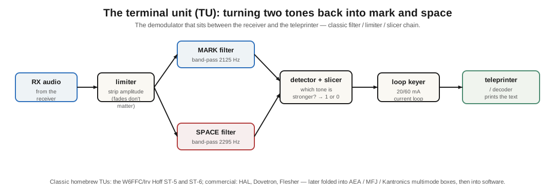
Your receiver gives you the two RTTY tones as audio; your teleprinter wants mark-and-space DC to drive its selector. The box that bridges them is the terminal unit (TU) — the RTTY demodulator — and its design is a small classic of analog engineering (Figure 1).
Follow the signal through it:
- Limiter — first, hard-limit the audio into a constant-amplitude square wave. Now a signal that’s fading up and down looks the same as a strong one; RTTY doesn’t care how loud the tones are, only which tone is present. (This is why RTTY punches through fading so well.)
- Two filters — a narrow band-pass MARK filter tuned to 2125 Hz and a SPACE filter tuned to 2295 Hz, each listening for its own tone.
- Detector and slicer — compare the two filter outputs: whichever is stronger wins, and a slicer (a comparator) cleanly decides mark or space, 1 or 0 — a good TU flips on a shift of just a hertz or two.
- Loop keyer — finally, key the teleprinter’s 20 or 60 mA current loop with that decision, and the machine prints.
2.2 The great terminal units
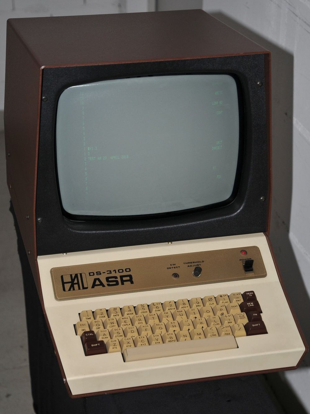
For decades a TU was a box you bought or, better, built. The definitive homebrew design was Irv Hoff, W6FFC’s “Mainline” series — the ST-5 and especially the ST-6 (1970), which a generation of hams etched, stuffed, and aligned on the kitchen table, and which is still a benchmark for how a discrete TU should work. On the commercial side, HAL Communications (the ST-6000, ST-8000, and their RS-2100 tuning scope), Dovetron, and Flesher made the boxes you’d find in a serious RTTY station. (Careful with the names: the homebrew ST-5/ST-6 are Hoff’s; the ST-6000/ST-8000 are HAL — different things despite the similar numbers.) Later, the TU’s whole job got folded into multimode data controllers from AEA, MFJ, and Kantronics, and finally into pure software — which is the next dive.
2.3 Tuning by eye: the crossed bananas
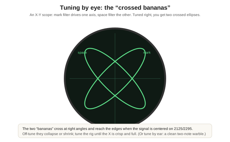
You can’t just spin the dial onto an RTTY signal by luck — you have to land the two tones exactly on 2125 and 2295. The classic way to do it is one of the loveliest instruments in ham radio: the “crossed bananas” tuning scope (Figure 2). It’s a little X-Y oscilloscope wired so the mark filter drives one axis and the space filter the other. Tune the rig right and you see two glowing green ellipses crossing at right angles — the “bananas” — reaching out to the edges of the screen. Off-tune, they collapse toward one axis, tilt, or shrink. You tune until the X is crisp, full, and upright, and then the machine prints clean copy.
You can also tune by ear — RTTY’s two-note warble has a distinctive pitch, and an experienced operator matches it to the diddle they know — and modern software shows the equivalent as two “railroad track” lines in a waterfall you drag your cursor between. But nothing ever looked as good as two green bananas crossing on a dark scope.
2.4 Running RTTY
A few pieces of the craft:
- RY RY RY — the standard test/tuning transmission. R (01010) and Y (10101) are exact opposites, so alternating them gives a rapid, even mark-space pattern that exercises every bit and mechanism and makes tuning easy. See “RY RY RY” scroll and you’ve found someone tuning up.
- “The quick brown fox jumps over the lazy dog” — the pangram test sentence that uses every letter, sent to check a machine end to end.
- Contesting and DXing — RTTY has a big, active contest following, exchanging signal reports and serial numbers or states at machine speed; chasing DX on RTTY is its own rewarding game.
2.5 Where RTTY came from and where it went
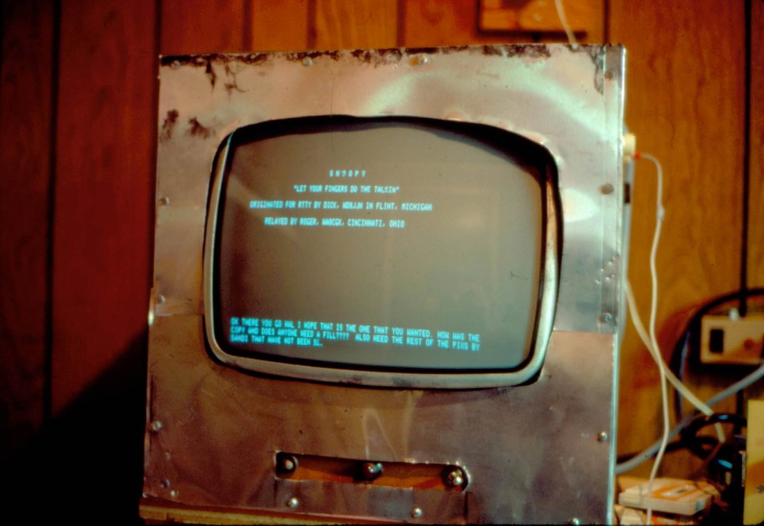
Amateur RTTY is nearly as old as the surplus that spawned it. The first two-way ham RTTY QSO was in May 1946 (W2AUF and W2BFD), using war-surplus mechanical teleprinters, and for decades the classic ham RTTY page printer was the Teletype Model 15 — the same cast-iron workhorse from the Teletype Machines dive (the very earliest surplus machines were often Model 26s, but the 15 is the one most hams pounded RTTY on). A ham RTTY station was a rig, a terminal unit, a tuning scope, and a clattering Model 15 in the corner — exactly the setup I grew up next to.
Honesty compels the coda: RTTY is no longer the king it was. Software weak-signal modes — PSK31, and above all FT8 (2017) — now carry most of the casual and weak-signal digital traffic that RTTY once did, because they get through when RTTY can’t and need almost no station. RTTY survives, and thrives, mainly in contests, where its speed and character still shine. But it never really left, and the next dive shows how the whole terminal unit — filters, slicer, crossed bananas and all — collapsed into a soundcard and a Raspberry Pi, so you can still run the two-tone warble I love with nothing but a modern radio and a $35 computer.
2.5.1 Sources (Vol 2)
- rtty.com, “Mainline ST-6” and “ST-5” — the classic TU architecture (limiter, mark/space discriminator filters, detector, slicer, loop keyer) and Irv Hoff W6FFC’s homebrew Mainline series (ST-5/ST-6, ~1970). https://www.rtty.com/development/tu/st-6/st-6.htm
- HAL Communications (ST-6000/ST-8000, RS-2100 scope) and Dovetron/Flesher as commercial TU makers; W6IWI TU references. The “crossed bananas” X-Y tuning display: Dhakajack “The Crossed Bananas Display”; HAL RS-2100.
- Wikipedia, “Radioteletype” — the RY RY test pattern (R 01010 / Y 10101), the “quick brown fox” pangram, first ham RTTY QSO (May 1946), surplus origins (Model 26 earliest; Model 15 the classic), and RTTY’s displacement by PSK31/FT8. https://en.wikipedia.org/wiki/Radioteletype