AM, SSB & the Voice Modes · Volume 2
AM, SSB & the Voice Modes — Vol 2: Throwing Away Two-Thirds of Your Signal
Suppress the carrier, delete one twin, and SSB gains 9 dB — not the 6 dB you usually read. And the famous explanation for why we use LSB below 10 MHz turns out to be arithmetically impossible.
2.1 Delete the useless parts
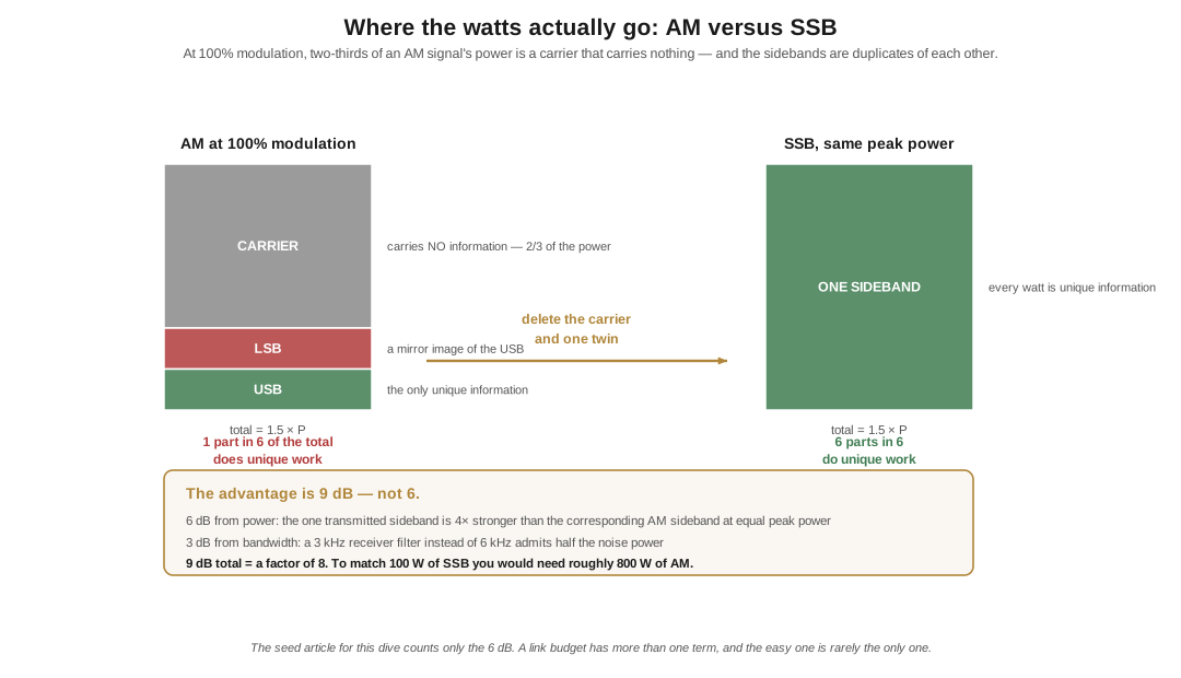
Volume 1 left AM convicted. Two-thirds of the power in a carrier that carries nothing; the remaining third split between two sidebands that are mirror-image duplicates of each other. One part in six of a fully modulated AM signal is doing unique work.
The obvious response — get rid of the carrier and one of the sidebands — was understood in principle in the 1910s and worked out properly during the 1930s. The receiving problem was the hard part, and it is worth understanding why.
The carrier is not information, but it is a reference. When a diode envelope detector demodulates AM, the carrier is quietly doing a job: it provides the frequency and phase reference against which the sidebands are interpreted. Delete it and the receiver has to supply its own — a locally generated carrier, at exactly the right frequency, reinserted at the detector. In an SSB receiver this is the BFO or carrier oscillator, and it is the same circuit that makes CW audible.
“Exactly the right frequency” is the catch, and it is why SSB had to wait. Get the reinserted carrier wrong by 50 Hz and every recovered speech component is shifted by 50 Hz — not stretched, shifted, which destroys the harmonic relationships that make a voice sound like a voice. This is the famous Donald Duck sound, and it is what you hear when you are tuned a few hundred hertz off an SSB signal, or when you are listening on the wrong sideband entirely. Human speech survives a shift of about ±50 Hz before it starts to sound odd, and ±100 Hz before it becomes work. Building oscillators that stable, and receivers that could be tuned that finely, took until during and after the Second World War. Once they existed, SSB replaced AM for point-to-point work with remarkable speed.
2.2 The 9 dB, and the missing 3 dB
Here is the first place the seed article for this sub-project comes up short, and the shortfall is instructive rather than embarrassing.
Ward Silver writes that putting all the power into one sideband gives “a four-fold (or 6 dB) improvement” in signal-to-noise ratio. The factor of four is right, the 6 dB is right, and the answer is incomplete, because there are two separate mechanisms at work and he has only counted one.
Mechanism one — the power. A transmitter is limited by its peak envelope power. Spend all of that PEP on a single sideband rather than dividing it between a carrier and two sidebands, and the one sideband you transmit is about four times stronger than the corresponding sideband of an AM signal of the same peak power. Four times is 6 dB.
Mechanism two — the bandwidth. An AM signal 6 kHz wide needs a receiver 6 kHz wide. An SSB signal is only 3 kHz wide, so the receiver’s filter can be half as wide — and a filter half as wide admits half the noise power, because noise is spread across the spectrum and you are now looking at half as much of it. Halving the noise is another factor of two, another 3 dB.
6 dB + 3 dB = 9 dB, and 9 dB is the figure the ARRL Handbook has quoted for decades. Nine decibels is a factor of eight in power. To match a 100-watt SSB station with AM you would need an 800-watt AM transmitter — which, since three-quarters of that would be sunk in the carrier and the spare twin, is exactly the sort of comparison that ended the argument in the 1950s.
The lesson is one I keep relearning across this whole project: a link budget has more than one term, and the easy one is rarely the only one. Ward counted the transmitter’s contribution and stopped. The receiver’s contribution was sitting right there.
2.3 LSB below, USB above — and the explanation that cannot be true
Either sideband works. They contain identical information; USB and LSB are functionally equivalent, and the choice is pure convention. But it is a convention you must obey, because a receiver set to the wrong sideband recovers the audio inverted — the spectrum flipped end for end — and inverted speech is not “hard to understand,” it is unintelligible. It sounds like a machine gargling. That is not a subtle effect and it is the fastest way to identify a mis-set radio.
The convention among hams is:
Table 1 — The convention among hams is
| Band | Sideband |
|---|---|
| 160 m, 80/75 m, 40 m | LSB |
| 60 m (5 MHz channels) | USB — by regulation, not habit |
| 20, 17, 15, 12, 10 m | USB |
| All VHF/UHF SSB | USB |
| Essentially all digital modes | USB |
Note two things immediately. First, the dividing line is usually stated as 10 MHz, not 9 — Ward’s article says 9 MHz, and that number is a fingerprint of the story I am about to take apart. Second, 60 metres breaks the pattern: it sits below 10 MHz and is USB anyway, because the channels were allocated recently and the regulators simply specified it.
Now the explanation everybody gives. It goes like this: early SSB rigs used a 9 MHz crystal filter and a 5.0–5.5 MHz VFO. Subtract and you land on 75 metres; add and you land on 20 metres. The subtraction inverts the sideband while the addition does not, so a single filter gave you LSB on 75 and USB on 20 for free, and we have been living with the consequences ever since.
It is a lovely story. It is repeated in club talks, in study guides, and in magazine columns. And it is arithmetically impossible.
🔴 Sideband inversion in a mixer has a precise condition. The sideband flips only when you form (local oscillator − signal) — when the modulated signal is subtracted from the unmodulated one. It does not flip when you form (signal − LO), and it does not flip when you form (signal + LO).
Work the numbers with a 9 MHz carrier, USB, and a tone putting a sideband component at 9.001 MHz, and a 5.2 MHz VFO:
- 75 m: 9.000 − 5.2 = 3.800; 9.001 − 5.2 = 3.801. The sideband is still above the carrier. Still USB. This is (signal − LO): no inversion.
- 20 m: 9.000 + 5.2 = 14.200; 9.001 + 5.2 = 14.201. Still above. Still USB.
Both outputs come out on the same sideband. The scheme that supposedly created the convention cannot create it. To get an inversion you would need the VFO above the IF — 12.8 MHz, say — which is not the story anyone tells.
Bill Meara, N2CQR, worked this through on SolderSmoke and has been trying to kill the myth since 2012. He has also, honestly, failed to find a satisfying replacement. What the record actually shows:
- The convention was already in use by 1958 — the Central Electronics 20A manual describes LSB as the sideband “most commonly used” on 75 and USB as preferred on 20.
- Its first formal appearance in the amateur literature seems to be the ARRL’s 1965 Single Sideband for the Radio Amateur, which notes with resignation that “there has been a species of standardization on the particular sideband used in the various amateur bands” and observes that making sideband selectable would “add appreciably to the cost of the equipment.” That is a book recording an existing habit, not creating one.
- Individual rigs really did have mixing schemes that produced the convention — the Swan 240 of 1963, for instance, used a 5174.5 kHz filter and a VFO arrangement that yielded LSB on 75 and 40 and USB on 20. So a version of the folk explanation is true of specific radios. It is just not true of the 9 MHz one everyone cites.
So the honest answer is: we do not know. It emerged in the mid-1950s from surplus gear, single-filter economics, and imitation, it was entrenched before anyone wrote it down, and by the time selectable sideband became free the cost of changing was infinite. I would rather record that plainly than repeat a tidy explanation that fails when you do the arithmetic. The corrections are the product.
2.4 Why AM is still on the air
SSB won the argument on efficiency and it did not win it on sound.
An AM signal has both sidebands and a full carrier, and a receiver demodulating it does not have to guess at anything. There is no reinserted-carrier error, no Donald Duck, no fatigue from a filter squeezing everything into 2.4 kHz. Wind the audio bandwidth out to 6 or 8 kHz and put it through a big speaker and AM sounds warm in a way that a communications-grade SSB signal simply does not — better bass, more presence, none of the processed edge.
There is a whole community that keeps the “big iron” running for exactly this reason: Collins and Johnson and Gates transmitters, homebrew plate-modulated rigs, a lot of glass and a lot of iron and a plate current meter that swings with your voice. They congregate around 3.885 MHz and 7.290 MHz and a few other traditional watering holes, they run relaxed round-table conversations rather than contacts, and the audio is genuinely lovely. It is the same instinct that keeps me pounding brass when FT8 would work a station I cannot hear: the efficient answer and the satisfying answer are not always the same one, and a hobby is allowed to choose.
That is amplitude, top to bottom. Next: the other two knobs, which turn out to be the same knob.
2.4.1 Sources (Vol 2)
- H. Ward Silver, N0AX, “Wireless Modes — Part 1,” Nuts & Volts, March 2017 — the 1930s carrier/sideband suppression work, the receiver supplying the missing carrier as a frequency and phase reference, the post-WWII adoption of SSB, the “four-fold (or 6 dB)” figure corrected here, the LSB/USB-at-9-MHz claim examined here, and the “That Warm AM Sound” sidebar. https://www.nutsvolts.com/magazine/article/March2017_HamsWirelessWorkbench_Wireless-Modes
- 🔴 The 9 dB figure: ARRL Handbook (long-standing; the 1988 edition is frequently quoted) — SSB shows an effective gain of up to 9 dB over an AM signal of the same peak power, decomposing as 6 dB of power advantage plus 3 dB from halving the receiver’s noise bandwidth. See also Electronics Notes, “What is SSB: Single Sideband Modulation.” https://www.electronics-notes.com/articles/radio/modulation/single-sideband-ssb-basics.php
- 🔴 The LSB/USB myth: Bill Meara N2CQR, SolderSmoke Daily News — “USB/LSB Urban Legend DEBUNKED!” (May 2012), “The Stubborn Myth about USB and LSB” (June 2021), and “So Where DID the LSB/USB Convention Come From?” (Sept 2021), which lays out the arithmetic, the 1958 Central Electronics 20A manual evidence, the 1965 ARRL Single Sideband for the Radio Amateur quotation, and the Swan 240 (1963) counter-example — and concludes the true origin is still unknown. https://soldersmoke.blogspot.com/2021/06/the-stubborn-myth-about-usb-and-lsb.html · https://soldersmoke.blogspot.com/2021/09/so-where-did-lsbusb-convention-come-from.html
- 60 m USB is a regulatory requirement, not a convention — see the current 47 CFR Part 97 and the ARRL 60 m band plan. ⟨verify against current rules before operating⟩
- Cross-links: How a Signal Carries Information Vol 2 (the
J3Edesignator); RTTY on the Air (the same sideband inversion, met in the audio domain); Building a Wireless-Modes Bench (hearing inverted speech for yourself on a WebSDR is a five-minute experiment).