AM, SSB & the Voice Modes · Volume 1
AM, SSB & the Voice Modes — Vol 1: Grabbing the Amplitude Knob
Morse code is amplitude modulation with only two settings. Turn the knob smoothly instead of slamming it, and you get AM — plus a pair of mirror-image sidebands that nobody asked for and everybody has to pay for.
1.1 The oldest mode is an amplitude mode
Of the three knobs from How a Signal Carries Information, amplitude was the first one anybody grabbed, because it is the one you can grab with a switch.
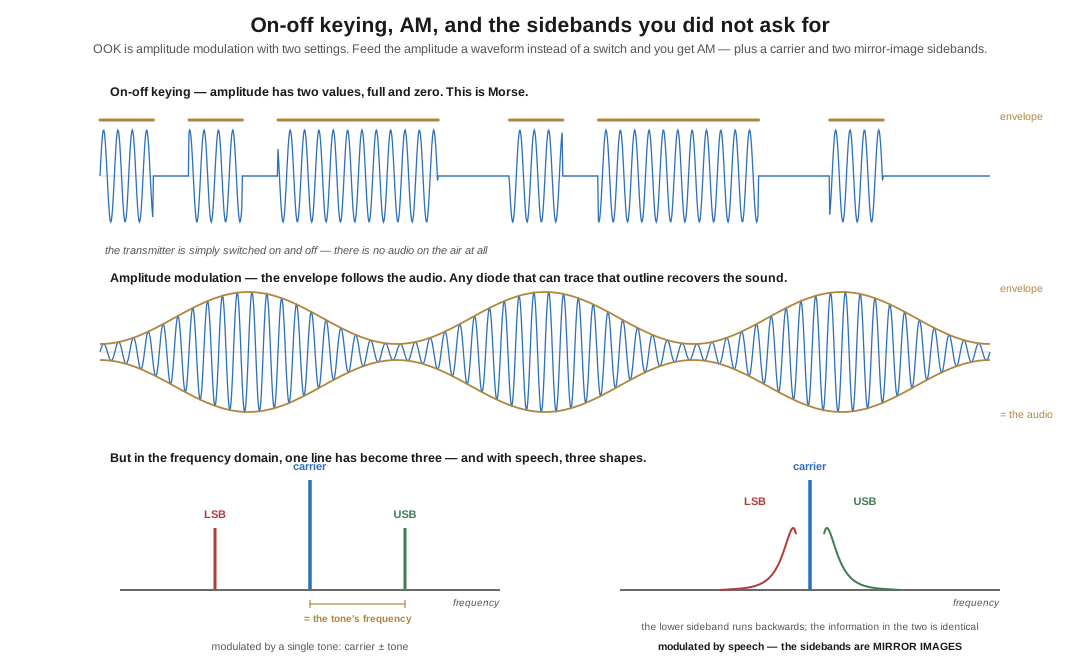
Turn a transmitter on. Turn it off. Turn it on again. Do it in a pattern that stands for letters, and you have the oldest wireless mode there is, and this project has spent fifteen dives on it already. Hams call it CW — from “continuous wave,” the term that distinguished a clean single-frequency signal from the broadband crash of a spark transmitter — and the engineers call it on-off keying, OOK. The keying part is literal in origin and figurative now: a transmitter is “keyed” whether there is a telegraph key in the circuit or a microcontroller pin.
But notice what OOK is, in the language of Volume 1. It is amplitude modulation with exactly two amplitudes: full and zero. It is the crudest possible member of the amplitude family, and its emission designator, A1A, says as much — amplitude modulated, one digital channel, telegraphy for aural reception.
In the frequency domain, a CW signal is that single vertical line from Volume 1 appearing and disappearing in the rhythm of the code. And the beeping you hear is not on the air at all: the transmitted signal has no audio content whatsoever. Your receiver’s beat frequency oscillator generates a tone by mixing the incoming carrier against a local oscillator a few hundred hertz away, so the presence of RF becomes an audible note and the absence becomes silence. Turn the BFO off and a CW signal is inaudible — which is why an AM broadcast receiver hears nothing but faint clicks on the CW portion of a band.
1.2 Turning the knob smoothly
Morse can carry a conversation but it cannot carry a voice. For that you need the amplitude to follow a waveform rather than a switch, and the recipe is straightforward enough that it was being done commercially before the First World War:
- Generate a steady unmodulated carrier.
- Make its amplitude larger and smaller in step with the audio waveform.
The result is amplitude modulation, A3E, and its defining feature is the envelope — the outline traced by the peaks of the RF. That outline is the audio. Any receiver that can follow the envelope recovers the sound, and following an envelope is so easy that a single diode does it. That is the whole trick behind a crystal set: a diode, a tuned circuit, an earpiece, no power supply at all. My generation built one from a kit; the generation before built one from a razor blade and a pencil.
Hams sometimes call AM “ancient modulation,” affectionately, and it deserves the affection. The simplicity is real. But look at what it does in the frequency domain and the bill arrives.
1.3 The sidebands nobody asked for
Modulate a carrier with a single audio tone and the spectrum is no longer one line. It is three:
- the carrier, unchanged, at its original frequency;
- an upper sideband (USB), above the carrier by the tone’s frequency;
- a lower sideband (LSB), below the carrier by the same amount.
The arithmetic is worth doing once by hand because it demystifies the whole thing. Carrier at 1.000 MHz, modulating tone at 1,000 Hz. The sidebands appear at 1.001 MHz and 0.999 MHz. Exactly one kilohertz either side. That is all a sideband is: the sum and difference frequencies that fall out of multiplying two sine waves together.
Now modulate with speech instead of a tone. Speech is not one frequency but a band of them, roughly 300 Hz to 3 kHz, so each component produces its own pair. The result is two bands flanking the carrier, each as wide as the speech itself — and an AM signal carrying 3 kHz of audio therefore occupies 6 kHz of spectrum, twice the width of the information it carries.
And they are mirror images. This is the detail worth pausing on. In the upper sideband, the low speech frequencies sit closest to the carrier and the high ones furthest away, in the order you would expect. In the lower sideband everything is inverted — the low speech frequencies still sit closest to the carrier, which means that as you read left to right across the spectrum, the lower sideband runs backwards. The two are reflections of each other about the carrier, and the information in them is identical.
Why the mirror matters later. This inversion is not a curiosity. It is the direct cause of the single most confusing thing in RTTY operating — that the mark tone is the lower audio frequency but the higher radio frequency when you work LSB. Same physics, met again in a different dive. See RTTY on the Air, Vol 1.
1.4 Modulation percentage, and the sound of a broken transmitter
How far you swing the amplitude is the modulation percentage. At 100% modulation the envelope just touches zero at the negative peaks and reaches twice the carrier amplitude at the positive peaks. That is the maximum you can do cleanly.
Push past it and the envelope tries to go negative, which a simple modulator cannot do — so it clips flat at zero instead. This is overmodulation, and it is audible from three counties away. Clipping a smooth waveform generates harmonics, harmonics generate new sidebands far outside the intended channel, and the result is splatter: a signal several times wider than it should be, distorted for the person you are talking to and interfering for everyone within a few kilohertz. If you have ever heard a station on 75 metres that sounds harsh and takes up half the band, you have heard someone with their microphone gain too high.
The mirror image of that fault is undermodulation — talking too quietly, so the envelope barely varies. Nothing splatters; you just waste nearly all your power on the carrier and are hard to hear. Which brings us to the real problem with AM.
1.5 The power audit that damns AM
Here is where AM stops being charming.
The carrier carries no information. It never varies. By Volume 1’s argument it is, by definition, telling the receiver nothing — and yet at 100% modulation it consumes two-thirds of the total transmitted power. Run the numbers: with carrier power P, each sideband at full modulation carries P/4, so the total is 1.5P — of which P is carrier and only P/2 is spread across two sidebands.
And the two sidebands are duplicates. They are mirror images containing identical information. Sending both is sending everything twice.
So of the power leaving the antenna of a fully modulated AM transmitter, the fraction doing genuinely unique, information-bearing work is one sideband out of 1.5P — one part in six. A kilowatt AM transmitter puts about 167 watts of unique information on the air. The rest is a carrier that says nothing and a spare copy nobody needs.
This was understood early and tolerated for decades, because the alternative required receiver technology that did not yet exist. Volume 2 is about what happened when it did: throwing away the carrier and one of the twins, and getting a 9 dB improvement for the trouble — not the 6 dB the seed article for this sub-project claims, and the difference between those two numbers is a genuinely instructive story.
1.5.1 Sources (Vol 1)
- H. Ward Silver, N0AX, “Wireless Modes — Part 1,” Nuts & Volts, March 2017 — OOK as the simplest form of AM, the carrier/envelope description, the sideband arithmetic (1 MHz carrier + 1 kHz tone → 0.999/1.001 MHz), the mirror-image sidebands, and the “one-fourth of the power in a unique signal” audit. Note this dive states the power fractions relative to total transmitted power (one part in six at 100% modulation), which is the same physics expressed against a different denominator. https://www.nutsvolts.com/magazine/article/March2017_HamsWirelessWorkbench_Wireless-Modes
- ARRL, Radio Technology Portal and the ARRL Handbook, modulation chapters — AM power distribution, modulation percentage, overmodulation and splatter. https://www.arrl.org/tech-portal
- Emission designators
A1A(Morse) andA3E(AM telephony): ITU Radio Regulations App. 1 / 47 CFR §2.201. See How a Signal Carries Information, Vol 2. - Cross-links: Morse & CW → The History of Morse Code and The Code, Timing & Abbreviations (OOK as a mode); RTTY on the Air (sideband inversion in practice); FM & Angle Modulation (the other two knobs).