FM and Angle Modulation · Volume 1
FM & Angle Modulation — Vol 1: The Other Two Knobs Are the Same Knob
Frequency and phase are not two things you can modulate. They are one thing, expressed two ways — and the sidebands that result are infinite in number, with a beautiful checkable fact hiding at a modulation index of 2.405.
1.1 φ is one variable
Back to the sine wave from the foundation dive:
s(t) = A · sin(φ) where φ = 2πft + θAmplitude modulation, the whole of the previous dive, varies A. Everything left is inside φ — and f and θ are not independent. Frequency is the rate at which phase advances. Change one and you have changed the other; there is no way to nudge a signal’s frequency without altering its phase, and no way to keep shifting its phase without that constituting a frequency change.
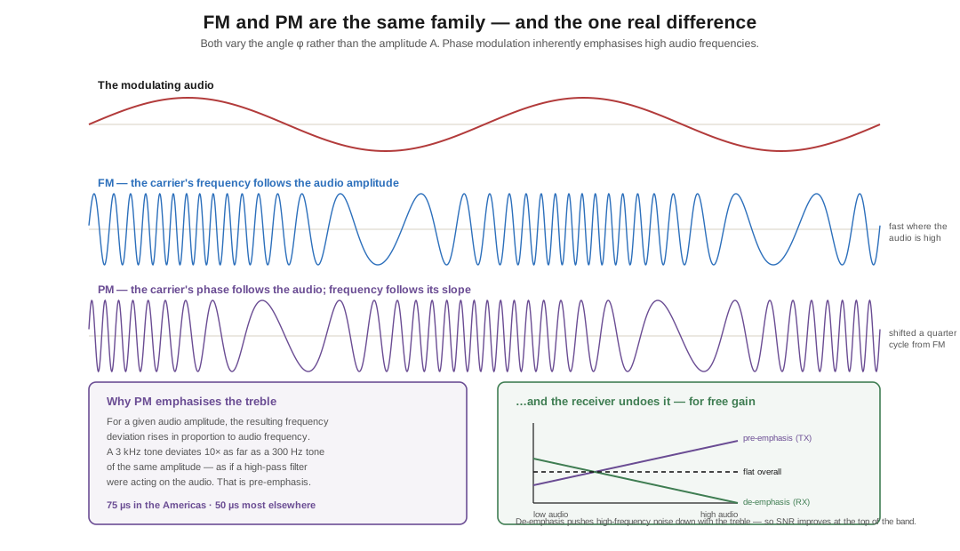
This is why frequency modulation and phase modulation are grouped together as angle modulation, and why the distinction between them is far smaller than the separate names suggest. Feed the same audio into an FM modulator and a PM modulator and you get two signals that are recognisably relatives — mathematically, PM of a signal is FM of that signal’s derivative, and FM is PM of its integral.
In hardware the difference is which reactance you wiggle: FM by varying a capacitance in a resonant circuit (classically a varactor across the oscillator tank), PM by varying the reactance of a phase-shifting network after the oscillator. That second approach has a practical advantage worth knowing — the oscillator can be a rock-stable crystal, because you are not touching it — and that is why an enormous amount of gear labelled “FM” is in fact phase-modulated.
1.2 The one real difference: pre-emphasis
There is exactly one behavioural difference that matters, and it falls out of the derivative relationship above.
Phase modulation inherently emphasises the high audio frequencies. For a given audio amplitude, the resulting frequency deviation rises in proportion to the audio frequency — a 3 kHz tone produces ten times the deviation of a 300 Hz tone of the same amplitude. The effect is exactly as if a high-pass filter were acting on the audio, and it has a name: pre-emphasis.
Left alone this would make PM sound thin and shrill. The fix is to build the complementary de-emphasis — a low-pass network with the matching time constant — into the receiver, restoring flat response.
And then somebody noticed you get something for free. Most of the noise a receiver adds is spread across the audio band, but the signal has been boosted at the top end before transmission and is therefore boosted relative to that noise. De-emphasising at the receiver pushes the high-frequency noise down along with the treble, and the signal-to-noise ratio at the top of the audio band improves. What began as an artefact of how PM works became a deliberate design feature, applied to FM systems too. Broadcast FM in the Americas uses a 75 µs time constant; most of the rest of the world uses 50 µs; amateur NBFM gear conventionally uses 6 dB per octave pre-emphasis above 300 Hz. Mismatch them and the audio sounds wrong in a way that is instantly recognisable once you know to listen for it.
From here on I will write FM and mean both, which is what everyone does.
1.3 Deviation and modulation index
Two numbers describe an FM signal, and confusing them is the most common mistake in the subject.
Deviation (Δf) is how far the carrier swings from its resting frequency, in hertz. It is set by the amplitude of the modulating audio — talk louder, deviate further. Broadcast FM is allowed ±75 kHz. Amateur narrowband FM on 2 m and 70 cm runs about ±5 kHz.
Modulation index (β) is the ratio of deviation to the modulating frequency:
        Δf        deviation, in Hz
  β  =  ───  =  ─────────────────────
        f_m     modulating frequency, in Hz
β is dimensionless, and it — not deviation alone — determines the shape of the spectrum. Note the consequence, which surprises people: for a fixed deviation, β falls as the audio frequency rises. A broadcast station deviating the full ±75 kHz has β = 5 on a 15 kHz tone and β = 250 on a 300 Hz tone. There is no single modulation index for a real signal carrying speech or music; it is changing continuously.
1.4 Infinite sidebands, and the null at 2.405
Now the part that makes FM genuinely strange compared to AM.
An AM carrier modulated by a single tone produces exactly two sidebands. Clean, finite, done. An FM carrier modulated by a single tone produces, in principle, an infinite number of sidebands — pairs spaced at every integer multiple of the modulating frequency, running away in both directions forever.
The amplitudes of the carrier and of each sideband pair are given by Bessel functions of the first kind, J₀(β) for the carrier and Jₙ(β) for the n-th sideband pair. You do not need to be able to evaluate a Bessel function to use this; you need three consequences of it.
First: the total power never changes. This is the property that separates FM from every amplitude mode. Modulating an FM transmitter does not add power — it redistributes power that was already there, moving it out of the carrier and into the sidebands. FM is a constant-power, constant-envelope signal. Key an FM transmitter and the output power is the same whether you are talking or silent. (Watch an SSB rig’s meter while you speak, then an FM rig’s, and the difference is immediate: the SSB needle dances with your voice, the FM needle sits still.)
Second: bandwidth grows with β. More index, more significant sidebands, wider signal. That is the whole reason narrowband and wideband FM exist as separate design points.
Third — and this is the lovely one — the carrier can vanish entirely. J₀(β), the carrier amplitude, is a decaying oscillation, and its first zero is at β = 2.405 (2.404826, to be precise). At that exact modulation index there is no carrier at all — every watt has moved into the sidebands. There are further nulls at β ≈ 5.520, 8.654, and onward.
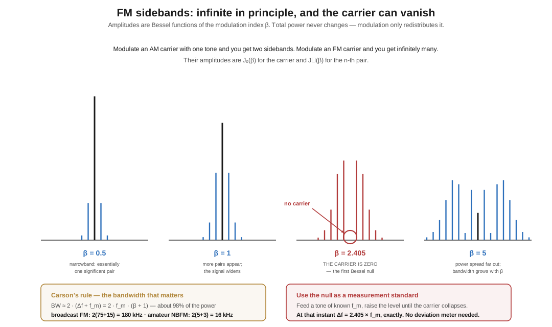
You can use this on the bench. The Bessel null is the classic way to calibrate deviation without a deviation meter. Feed a modulating tone of known frequency f_m, watch the carrier on a spectrum analyser, and raise the audio level until the carrier collapses into the noise. At that instant β = 2.405, so the deviation is Δf = 2.405 × f_m exactly. Modulate with a 1,000 Hz tone and null the carrier and you know you are deviating 2,405 Hz — no calibrated instrument required, just a frequency-accurate tone and the ability to see a null. It is one of my favourite pieces of test technique in all of radio: a mathematical constant, used as a measurement standard, visible on a screen.
1.5 Carson’s rule: the bandwidth that actually matters
“Infinite sidebands” is true and useless for engineering. In practice the distant sidebands are vanishingly small, and the working answer is Carson’s rule:
BW ≈ 2 · (Δf + f_m) = 2 · f_m · (β + 1)— the bandwidth containing about 98% of the signal power. Two examples, both worth committing to memory:
Table 1 — — the bandwidth containing about 98% of the signal power. Two examples, both worth committing to memory
| Deviation | Max audio | β | Carson bandwidth | |
|---|---|---|---|---|
| Broadcast FM | ±75 kHz | 15 kHz | 5 | 2(75+15) = 180 kHz |
| Amateur NBFM | ±5 kHz | 3 kHz | ~1.7 | 2(5+3) = 16 kHz |
Which is why FM broadcast stations are spaced 200 kHz apart, and why an amateur NBFM signal has the emission designator 16K0F3E — 16.0 kHz, frequency modulation, one analogue channel, telephony. The designator is Carson’s rule, rounded, written down.
(A note on the seed article: Ward gives wideband broadcast FM as “a modulation index of 10 or more” occupying “up to 150 kHz.” The index figure depends entirely on which audio frequency you evaluate it at — it is 5 at the top of the audio band and far higher at the bottom — and 150 kHz undercounts; the standard Carson figure is 180 kHz, and the channel allocation is 200 kHz. Not wrong so much as imprecise about a quantity that is inherently slippery.)
Volume 2 is about why anyone put up with all this complexity — the limiter, the capture effect, and the reason a strong FM signal in a thunderstorm is silent while an AM signal is unusable.
1.5.1 Sources (Vol 1)
- H. Ward Silver, N0AX, “Wireless Modes — Part 1,” Nuts & Volts, March 2017 — angle modulation as the family containing FM and PM, the A sin(φ) framing, PM’s pre-emphasis and the receiver’s de-emphasis, Bessel functions setting the sideband amplitudes, FM as a constant-power signal, and the carrier null at an index of 2.4. https://www.nutsvolts.com/magazine/article/March2017_HamsWirelessWorkbench_Wireless-Modes
- Bessel null: the first zero of J₀ is at 2.404826 (standard mathematical constant; see any table of Bessel function zeros). Its use for deviation calibration is long-standing test practice.
- Carson’s rule and the worked bandwidths: Electronics Notes, “FM Sidebands & Frequency Modulation Bandwidth” — ±75 kHz deviation with 15 kHz maximum audio gives 2(75+15) = 180 kHz containing ~98% of the power; a 5 kHz-deviation, 3 kHz-audio two-way signal gives 16 kHz. https://www.electronics-notes.com/articles/radio/modulation/frequency-modulation-fm-sidebands-bandwidth.php · Wikipedia, “Carson bandwidth rule” (→ its citations).
- Pre-emphasis time constants: 75 µs in the Americas / South Korea, 50 µs in most of the rest of the world (ITU-R and national broadcast standards). ⟨verify against the current broadcast standard for any jurisdiction you care about⟩
- Cross-links: How a Signal Carries Information Vol 1 (the three knobs) and Vol 2 (
F3E,16K0F3E); AM, SSB & the Voice Modes (the amplitude knob, for contrast).