Building a Wireless-Modes Bench · Volume 2
Building a Wireless-Modes Bench — Vol 2: Transmit, and Five Things to Build
The interface between a computer and a transmitter is three components and one principle: isolate everything. Then five projects, from an evening's soldering to a beacon that will be heard on another continent overnight.
2.1 Read this part first
Everything in Volume 1 was legal for anybody. This volume is not. Transmitting on the amateur bands requires a licence, in every country, without exception, and there is no grey area. In the US that is an FCC Technician, General, or Amateur Extra licence; the Technician exam is thirty-five questions, the study material is free, and it takes most people a couple of weeks. Cross-link: Learning & Operating CW has my views on getting started.
Three more things that are not negotiable, stated once and meant:
- A dummy load is not optional. Every experiment in this volume that generates RF should be done into a 50-ohm dummy load first, and only then near an antenna.
- A low-pass filter is not optional for any of the square-wave transmitters described below. A microcontroller pin driving a wire is a superb generator of odd harmonics — the third and fifth are down only about 10 and 14 dB — and putting that on the air is illegal, antisocial, and can interfere with things that matter, like aviation. Filter it or do not key it.
- RF burns are real and they hurt in an unpleasantly deep way. So is the mains side of a linear supply. Treat both accordingly.
2.2 The whole art is isolation
Here is the transmit problem in one sentence. You need to get audio from the computer into the transmitter, audio from the receiver into the computer, and a push-to-talk signal from the computer to key the transmitter — and if you connect any of those three with a plain wire, you will create a ground loop.
A ground loop happens because the computer and the radio are each grounded, separately, and a direct audio connection creates a second path between them. Mains hum flows along it, and RF from your own transmitter flows back along it into the computer’s audio circuitry. The symptoms are unmistakable and maddening:
- Hum on your transmitted audio, reported by everyone you work.
- The computer locking up, the mouse jumping, or USB devices disconnecting whenever you key up — classic RF feedback.
- Distorted or wandering audio levels; a transmitter that keys and will not unkey.
The cure for all of it is galvanic isolation on all three paths. No DC connection between computer and radio anywhere. This is the entire design principle of every commercial interface ever sold, and it is why a homebrew one is three components and a box:
- Audio in and audio out each go through a small 1:1 audio isolation transformer, 600Ω:600Ω. These are a couple of dollars each. They pass audio and block DC and mains hum completely.
- PTT goes through an optocoupler — a 4N35, a PC817, anything ordinary — driven from a serial port’s RTS or DTR line (or a USB-serial adapter’s), with its transistor output switching the radio’s PTT line to ground. Light crosses the gap; electricity does not.
- Level control: a trimmer potentiometer on each audio path. This matters more than people expect — overdriving a transmitter’s audio input generates splatter exactly as in AM, SSB & the Voice Modes, and an overdriven digital signal is a wide, distorted, unpopular thing. Set your drive so the ALC meter barely moves.
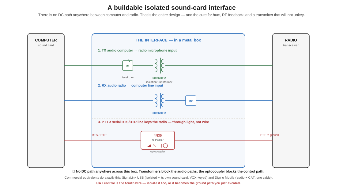
The commercial versions do exactly this: the SignaLink USB (isolated interface plus its own sound card, VOX-keyed so it needs no serial line), and the Digirig Mobile, which is smaller, cheaper, and combines the audio interface with CAT control on one USB cable. Both are excellent and both cost more than the parts. Build one first anyway — you will understand every failure mode afterwards.
CAT control — the serial link that lets software read and set the radio’s frequency and mode — is the fourth wire, and it needs isolating too, or it becomes the ground path you carefully avoided on the other three. Most modern radios have a USB port that presents both an audio device and a serial port; that is convenient, and it is also a direct connection, so a good USB isolator or generous common-mode chokes on the cable are worth having.
2.3 Five things to build
Roughly in order of difficulty.
2.3.1 The isolated interface (an evening)
Build the circuit above. Two transformers, an optocoupler, two trimmers, a resistor, and a diode across the PTT line, in a metal box. Test it into a dummy load with your rig on minimum power, watching the ALC. When your first PSK31 signal comes back clean off a WebSDR — you transmitting in your shack, listening to yourself on a receiver in another country — you have built a working digital station and you know exactly how every part of it works.
2.3.2 A Si5351 signal generator (a weekend)
The Si5351A is a $2 clock-generator chip that synthesises three independent square-wave outputs from about 8 kHz to 160 MHz, controlled over I²C. Breakout boards are a few dollars; the Arduino and Raspberry Pi libraries are mature.
With one of these and a microcontroller you can build a frequency-agile signal source for the whole HF spectrum. As a piece of test gear it is worth having on its own — an accurate signal at any frequency you like, for aligning receivers and checking filters. As a transmitter it is the front half of most modern QRP kits.
Two cautions. It puts out square waves, so the harmonic content is enormous — dummy load and low-pass filter, always. And its accuracy is only as good as its reference crystal, so a TCXO version is worth the extra dollars if you intend to do anything that cares about frequency, which is all of the weak-signal family.
2.3.3 A WSPR beacon (a weekend, and then it runs forever)
This is the project I recommend most often, because the payoff is out of all proportion to the effort.
Combine a Si5351, a microcontroller, a GPS module (for a disciplined clock and an automatic grid square), and a low-pass filter, and you have a beacon that transmits your callsign, grid, and power for 110 seconds every few minutes. Leave it running overnight. In the morning, open wsprnet.org and look at your map.
A few hundred milliwatts routinely crosses oceans on 30 metres. Twenty milliwatts has done it. There is no experience in radio quite like waking up to find that a circuit on your bench, running on less power than a laser pointer, was heard in Australia at 3 a.m.
The ready-made version is the QRP Labs kit line — Hans Summers, G0UPL — whose beacon and digital-mode kits are exceptional value and superbly documented. The QDX is a four-band 5 W digital transceiver kit with an embedded SDR receiver, a USB sound card, CAT control, and a Class-D power amplifier that generates the transmit signal by measuring the incoming audio tone and programming the Si5351 directly — no sideband modulator, no filter, just a synthesiser and a switching PA. It is a beautiful piece of design and a direct, physical illustration of the FSK-generation argument in The Shift-Keying Family: it does not modulate a carrier at all, it simply retunes one.
2.3.4 rpitx — the Pi as a transmitter (an afternoon, with care)
rpitx, by Évariste Courjaud F5OEO, is a piece of software that turns a Raspberry Pi’s GPIO pin into a radio transmitter across roughly 5 kHz to 1500 MHz, using the Pi’s clock hardware. It can generate FM, SSB, FSK, and can play WSPR and other modes directly.
It is a wonderful demonstration and a genuinely filthy transmitter. The output is a square wave straight off a digital pin, with harmonics across the entire spectrum and no filtering at all. Use it as a teaching instrument — into a dummy load, at low level, with a band-pass or low-pass filter if it goes anywhere near an antenna, and only on a band you are licensed for. Treat “I put a wire on the GPIO pin” as the thing you do not do.
2.3.5 Close the loop end to end (an evening, and the best one)
The project that ties the entire sub-project together, and the one I would do first if I were starting again.
- Generate a PSK31 or FT8 signal in software.
- Transmit it at milliwatts into a dummy load.
- Receive the leakage on your RTL-SDR on the other side of the bench.
- Watch it appear on the waterfall — your narrow line, your synchronised block.
- Decode it in fldigi or WSJT-X and read your own callsign coming back.
Nothing leaves the room. You need no licence to do it into a dummy load at that level in most jurisdictions ⟨verify for yours — the rules on incidental radiation vary and I am not your lawyer⟩. And you will have personally operated every single layer of the mode stack from How a Signal Carries Information: you chose the information, you generated the air link, you ran the protocol, and you decoded it back to text. Change the mode and watch the waterfall change. Detune the receiver 200 Hz and watch the decode fail. Turn the drive up too far and watch your own signal splatter across the display.
That last experiment in particular is worth doing deliberately, because seeing your own signal go wide is the fastest way to learn to keep it narrow — and it is a lesson best learned into a dummy load rather than from an annoyed stranger on 20 metres.
2.4 Where this leaves us
Six dives ago this sub-project started with a steady, meaningless whistle on 20 metres. What separates that whistle from a voice, from a file, from a callsign pulled out of noise 125 times stronger than itself, is nothing but a set of agreements about how to wobble it — and every one of those agreements is documented, buildable, and yours to experiment with, because in the mid-1990s a regulator decided that publishing the design was enough.
The instrument my father used to send text over the air had a brass lever, a spring, and a pair of contacts. The instrument on my bench has an LDPC decoder in it. They are doing the same thing. That is the argument of this whole project, and this is the sub-project where the machinery of it is finally visible.
2.4.1 Sources (Vol 2)
- H. Ward Silver, N0AX, “Wireless Modes — Part 2,” Nuts & Volts, May 2017 — the closing argument that amateur radio has become “a hotbed of mode and protocol experimentation,” and the invitation to apply your talents to it. https://www.nutsvolts.com/magazine/article/wireless-modes-part-2
- Isolation practice — audio transformers on both audio paths and an optocoupler on PTT is the standard construction of every commercial sound-card interface; see the ARRL Handbook’s digital-modes chapter and the SignaLink and Digirig documentation. https://www.tigertronics.com/ · https://digirig.net/
- Si5351A: Skyworks (formerly Silicon Labs) clock generator, ~8 kHz–160 MHz, I²C controlled, square-wave outputs. ⟨read the datasheet for the current part; output level and harmonic content are the specifications that matter here⟩
- QRP Labs — Hans Summers G0UPL. The QDX is a four-band (80/40/30/20 m) 5 W digital-modes transceiver kit with an embedded SDR receiver, 24-bit 48 ksps USB sound card, CAT control, TCXO-referenced synthesised VFO, a Tayloe quadrature mixer on receive, and a Class-D PA on transmit, generating FSK by retuning the Si5351 to match the measured audio tone. https://qrp-labs.com/ · build notes: http://wb6cxc.com/?p=244
- rpitx — Évariste Courjaud F5OEO. https://github.com/F5OEO/rpitx ⟨the frequency range and mode list change between releases; check the README⟩
- WSPR reporting and mapping: https://wsprnet.org
- 🔴 Legal note: transmitting on amateur frequencies requires a licence everywhere. Power limits, band segments, bandwidth limits (see the 2.8 kHz limit from FCC 23-93 in How a Signal Carries Information, Vol 2) and spurious-emission requirements are all binding. Read the current 47 CFR Part 97, or your national equivalent, before building anything in this volume that radiates.
- Cross-links: Building Your Own Keys (the same build-it-yourself instinct, applied to brass); Modern Digital & the Raspberry Pi; How a Signal Carries Information (the mode stack this volume lets you operate by hand).